HP Superdome SX2000 Installation Guide, Sixth Edition - HP Integrity Superdome - Page 64
Performing a Visual Inspection and Completing the Installation, Attaching Rear Kick Plates - cell board
 |
View all HP Superdome SX2000 manuals
Add to My Manuals
Save this manual to your list of manuals |
Page 64 highlights
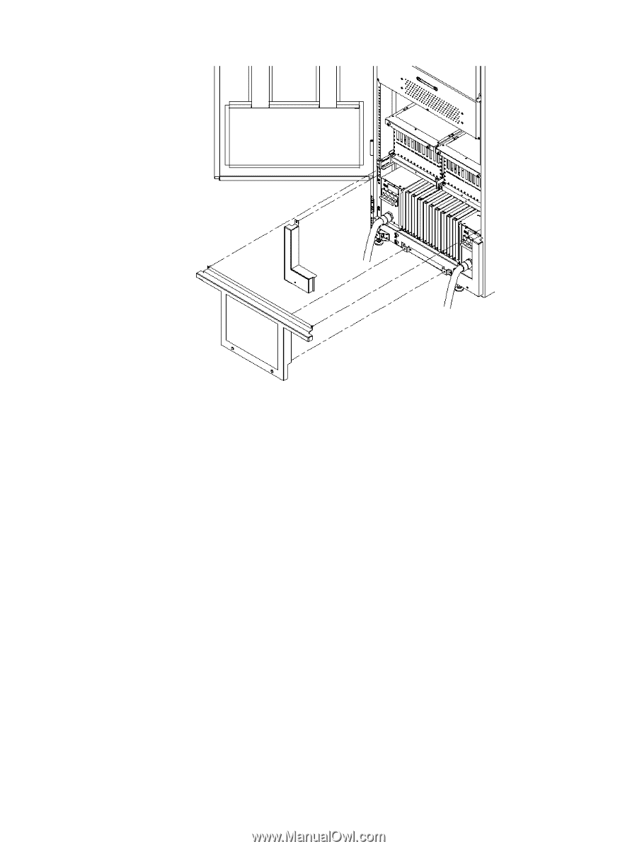
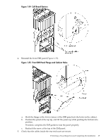
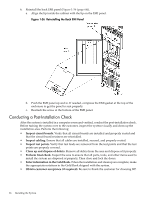
Figure 1-53 Attaching Rear Kick Plates 4. Perform steps 1-3 on the right kick plate. 5. Position the upper flange of the center kick plate under the I/O trays complementary mounting bracket, to retain the center kick plate top flanges. No top screws are needed on the center kick plate. Orient this asymmetrical bracket with the hole located nearest the edge in the up position. 6. Using a T-20 driver, tighten the thumbscrews at the bottom of the center kick plate. Performing a Visual Inspection and Completing the Installation After booting the system, carefully inspect it and reinstall the EMI panels. To perform a final inspection and complete the installation, follow these steps: 1. Visually inspect the system to verify that all components are in place and secure. 2. Check that the cables are secured and routed properly. 3. Check that the cell board ejectors are secure (Figure 1-54). If the ejectors are broken or open, the cell board is disconnected. 64 Installing the System
-
 1
1 -
2
-
3
-
4
-
5
-
6
-
7
-
8
-
9
-
10
-
11
-
12
-
13
-
14
-
15
-
16
-
17
-
18
-
19
-
20
-
21
-
22
-
23
-
24
-
25
-
26
-
27
-
28
-
29
-
30
-
31
-
32
-
33
-
34
-
35
-
36
-
37
-
38
-
39
-
40
-
41
-
42
-
43
-
44
-
45
-
46
-
47
-
48
-
49
-
50
-
51
-
52
-
53
-
54
-
55
-
56
-
57
-
58
-
 59
59 -
 60
60 -
 61
61 -
 62
62 -
 63
63 -
 64
64 -
 65
65 -
 66
66 -
 67
67 -
 68
68
 |
 |