HP VA 7400 Disk System/Configuration Specific Instructions
HP VA 7400 Manual
 |
View all HP VA 7400 manuals
Add to My Manuals
Save this manual to your list of manuals |
HP VA 7400 manual content summary:
- HP VA 7400 | Disk System/Configuration Specific Instructions - Page 1
. (See Chapter 3 of the HP StorageWorks Virtual Arrays VA 7000 Family User's and Service Guide for troubleshooting procedures.) Disks must be Fibre Channel (FC) and 3.5 inches wide but can vary in capacity. For current information about supported disks, consult an HP sales representative. You do not - HP VA 7400 | Disk System/Configuration Specific Instructions - Page 2
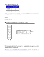
520-byte sectors. Table 1 indicates the times required for formatting the different capacity disks. Note Depending on the total amount of memory in your array and your specific configuration, a complete format and rebuild process may take between 4 and 24 hours. As per Step 11 (below) monitor your - HP VA 7400 | Disk System/Configuration Specific Instructions - Page 3
will flash during an Auto Format process. The amber system fault LED will also flash. If you observe different results, further Troubleshooting may need to be carried out. (See Chapter 3 of the HP StorageWorks Virtual Arrays VA 7000 Family User's and Service Guide for troubleshooting procedures.) 3 - HP VA 7400 | Disk System/Configuration Specific Instructions - Page 4
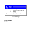
fault. Disk drive fault. Disk drive self-test in progress or I/O activity. Host is identifying disk drive. *Controlled by the disk drive. **Controlled by the array controller. Procedure Completed! "Congratulations!" 4
-
 1
1 -
 2
2 -
 3
3 -
 4
4
 |
 |
1
Replacement Procedure: VA7.x Disk Module, 18GB-36GB-72GB
You can add or replace disks to increase storage capacity or eliminate faults. (See Chapter 3 of the
HP StorageWorks Virtual Arrays VA 7000 Family User’s and Service Guide
for troubleshooting procedures.)
Disks must be Fibre Channel (FC) and 3.5 inches wide but can vary in capacity.
For current information about supported disks, consult an HP sales representative.
You do not need to turn off the array to replace a disk or filler.
Caution
Do not remove hot-pluggable components until you have the
replacement parts and are ready to install them.
An empty slot will cause
uneven cooling and eventual overheating.
Caution
Parts can be damaged by electrostatic discharge.
Please ensure
that ESD measures are in place.
Step 1
Open the Disk Replacement Kit and inspect the contents per the first step of the Disk Replacement Sheet
included with the replacement drive.
Step 2
Caution
Touching exposed electrical circuitry on the disk can damage the disk.
Be sure you are grounded
and be careful not to touch exposed circuits.
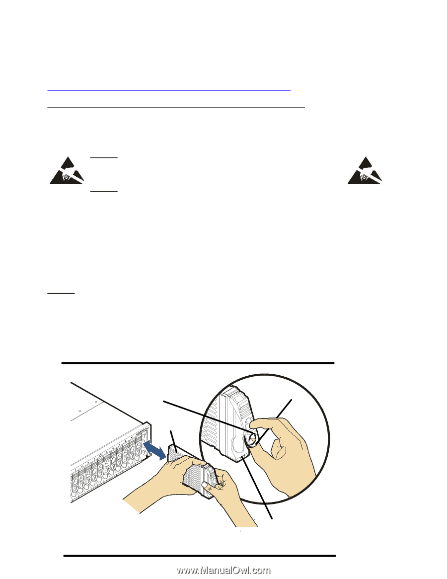
Disk modules are fragile and ESD sensitive. Dropping one end of the disk just two inches is enough to cause
permanent damage. In addition, static electricity can damage the disc. Grasp disks only by their handles (A
in Figure 1) and carriers (D), and follow strict ESD procedures.
Figure 1:
Disk Module Installation
B
C
A
D
A
extraction handle
C
LEDs
B
cam latch
D
carrier