HP Visualize J5000 hp Visualize J5000 to J5600 workstation PA8600 upgrade inst
HP Visualize J5000 - Workstation Manual
 |
View all HP Visualize J5000 manuals
Add to My Manuals
Save this manual to your list of manuals |
HP Visualize J5000 manual content summary:
- HP Visualize J5000 | hp Visualize J5000 to J5600 workstation PA8600 upgrade inst - Page 1
HP Visualize J5600 UNIX® Workstations PA8600 Upgrade Instructions Manufacturing Part Number: A5998-90000 Edition E1299 © Copyright 1999 by Hewlett-Packard - HP Visualize J5000 | hp Visualize J5000 to J5600 workstation PA8600 upgrade inst - Page 2
not furnished by Hewlett-Packard. Hewlett-Packard Warranty Statement Refer to Warranty & Support for your HP Workstation for warranty terms applicable to your Hewlett-Packard product and replacement parts. Restricted Rights Legend Use, duplication, or disclosure by the U.S. Government Department of - HP Visualize J5000 | hp Visualize J5000 to J5600 workstation PA8600 upgrade inst - Page 3
This software and documentation is based in part on the Fourth Berkeley Software Distribution under license from the Regents of University of California. 3 - HP Visualize J5000 | hp Visualize J5000 to J5600 workstation PA8600 upgrade inst - Page 4
4 - HP Visualize J5000 | hp Visualize J5000 to J5600 workstation PA8600 upgrade inst - Page 5
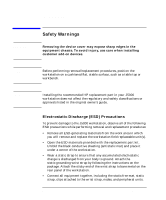
1 Getting Started The following important information must be adhered to for proper removal and replacement of all Hewlett-Packard parts. 5 - HP Visualize J5000 | hp Visualize J5000 to J5600 workstation PA8600 upgrade inst - Page 6
HP replacement part in your J5000 workstation does not affect the regulatory and safety classifications or approvals listed in the original owner's guide by following the instructions on the package. Attach the sticky end of the wrist strap to bare metal on the rear panel of the workstation. • Connect - HP Visualize J5000 | hp Visualize J5000 to J5600 workstation PA8600 upgrade inst - Page 7
antistatic bags, handle the printed circuit boards by their edges only. • Ensure you have a sufficient ESD protected area on which to lay out the parts you remove from the system. Chapter 1 7 - HP Visualize J5000 | hp Visualize J5000 to J5600 workstation PA8600 upgrade inst - Page 8
contents: • System board upgrade tray assembly • Electrostatic Discharge (ESD) materials • Removal/Replacement Instructions If you are missing any part or any documentation, please call your designated service representative. Required Tools You will need the following tools for removal/replacement - HP Visualize J5000 | hp Visualize J5000 to J5600 workstation PA8600 upgrade inst - Page 9
and should be performed in the sequence listed. Refer to individual sections of this guide for step-by-step procedures for upgrading a J5000 to a J5600. 1. Prepare your workstation - Verify that you have the correct version of HP-UX. - Determine and WRITE DOWN the LAN ID of your system. You may need - HP Visualize J5000 | hp Visualize J5000 to J5600 workstation PA8600 upgrade inst - Page 10
-UX. 1. Determine the workstation's LAN ID by entering the following command: /usr/sbin/lanscan. The output is similar to the following: Hardware Station Crd Hardware Net-Interface NM MAC HP DLPI Mjr Path Address In# State NameUnit State ID Type Support Num 2.0.2 0x08000970ECC0 0 UP lan0 UP 4 ETHER - HP Visualize J5000 | hp Visualize J5000 to J5600 workstation PA8600 upgrade inst - Page 11
CAUTION NOTE Getting Started Safely Powering Down the J5000 Workstation Safely Powering Down the J5000 Workstation You must complete the following steps before performing any of the removal and replacement procedures: Do not use the power supply interlock thumbscrew on the - HP Visualize J5000 | hp Visualize J5000 to J5600 workstation PA8600 upgrade inst - Page 12
Getting Started Product Exploded Diagram Product Exploded Diagram Refer to the figure below for a basic parts overview of the J5000/J7000 workstation. Top panel Flex cable retainer Flex cable DC/DC converter units and tie downs for J7000 Left side panel DDS-3/floppy EMI cover Chassis Right - HP Visualize J5000 | hp Visualize J5000 to J5600 workstation PA8600 upgrade inst - Page 13
2 System Board Removal/Replacement This chapter describes how to remove and replace the System Board for the J5000 workstation. 13 - HP Visualize J5000 | hp Visualize J5000 to J5600 workstation PA8600 upgrade inst - Page 14
System Board Removal/Replacement Removing the Front Panel Figure 2-1 Removing the Front Panel 1. Power down your workstation as described in "Getting Started." If locked, unlock the door on the front of the system and swing it to the right (see Step 1 in - HP Visualize J5000 | hp Visualize J5000 to J5600 workstation PA8600 upgrade inst - Page 15
Figure 2-2 Front Panel Removed System Board Removal/Replacement Removing the Front Panel Panel Hinge Holes Panel-Detach Screw Holes Chapter 2 15 - HP Visualize J5000 | hp Visualize J5000 to J5600 workstation PA8600 upgrade inst - Page 16
2 Top Panel 3 Right Side Panel Left Side Pane Hole for T-15 Torx Thumbscrew 3 (Power Supply Interlock) 1 2. Slide the top panel toward the back of the workstation. Lift up to remove it. Set the panel and screws aside. 3. Tip one of the side panels out and away from the chassis. Lift it - HP Visualize J5000 | hp Visualize J5000 to J5600 workstation PA8600 upgrade inst - Page 17
Figure 2-4 System Board Removal/Replacement Removing the Top and Side Panels Disconnecting the Flex Cable 1. Locate the flex cable. 2. Remove the flex cable retainer by grasping it and lifting up as shown below. Removing the Flex Cable Retainer 3. Remove the flex cable by grasping the connector - HP Visualize J5000 | hp Visualize J5000 to J5600 workstation PA8600 upgrade inst - Page 18
System Board Removal/Replacement Removing the Bus Bar Shield Removing the Bus Bar Shield 1. Remove the bus bar shield by pulling outward on its latch, and then lifting it up. This shield can be used to hold the screws you will remove in the next step. Figure 2-5 Removing the Bus Bar Shield Step - HP Visualize J5000 | hp Visualize J5000 to J5600 workstation PA8600 upgrade inst - Page 19
System Board Removal/Replacement Removing the Memory Card(s) (DIMMs) Figure 2-6 Removing the Memory Card(s) (DIMMs) 1. Press downward on the ejector tabs located on each side of the memory card (DIMM) slot. Removing a DIMM Ejector Tab Ejector Tab 2. Grasp the memory card by its edges and lift - HP Visualize J5000 | hp Visualize J5000 to J5600 workstation PA8600 upgrade inst - Page 20
System Board Removal/Replacement Disconnecting the System Board Cables Figure 2-7 Disconnecting the System Board Cables Location of the Cable Connections F The location of the cables is shown above. The cables are keyed. Squeeze the clips to unlock each cable. 20 Chapter 2 - HP Visualize J5000 | hp Visualize J5000 to J5600 workstation PA8600 upgrade inst - Page 21
system damage, make sure your static-grounding strap is securely attached to your wrist and to the bare metal on the workstation. Removing the Old System Board 1. Ensure all workstation cables are out of the way to avoid interference or damage when you remove the system board tray. Removing the - HP Visualize J5000 | hp Visualize J5000 to J5600 workstation PA8600 upgrade inst - Page 22
board tray's keyholes with the standoffs on the center wall of the chassis, and then slide the system board tray toward the back of the workstation to seat the standoffs into their corresponding keyholes. 2. Replace the two T-15 Torx screws that secure the system board tray to the rear wall of - HP Visualize J5000 | hp Visualize J5000 to J5600 workstation PA8600 upgrade inst - Page 23
System Board Removal/Replacement Reconnect the System Board Cables Figure 2-9 Reconnect the System Board Cables Location of the Cable Connections F The location of the cables is shown above. Chapter 2 23 - HP Visualize J5000 | hp Visualize J5000 to J5600 workstation PA8600 upgrade inst - Page 24
firmly and evenly push down on each side to lock it into place. the ejector tabs will angle upward as the memory card is inserted. 4. Visually inspect and confirm the connection between the memory card and the system board. 5. Repeat steps 1 and 2 for all memory cards. 24 Chapter 2 - HP Visualize J5000 | hp Visualize J5000 to J5600 workstation PA8600 upgrade inst - Page 25
System Board Removal/Replacement Replace the Bus Bar Shield Replace the Bus Bar Shield 1. Replace the four T-15 Torx thumbscrews from the power supply bus bar. The bus bar screws are longer than the other T-15 Torx screws. Figure 2-10 Replace the Bus Bar Shield Step 1: Replace the Bus bar Screws - HP Visualize J5000 | hp Visualize J5000 to J5600 workstation PA8600 upgrade inst - Page 26
System Board Removal/Replacement Reconnecting the Flex Cable Figure 2-11 Reconnecting the Flex Cable Align the flex cable connectors with the slots on the board. Seat firmly. Reconnecting the Flex Cable. Figure 2-12 Replace the flex cable retainer. Replace the Flex Cable retainer. 26 Chapter 2 - HP Visualize J5000 | hp Visualize J5000 to J5600 workstation PA8600 upgrade inst - Page 27
Replacing the Top and Side Panels Figure 2-13 Replacing the Top and Side Panels 1. Replace the side panels. Back View of the Workstation 2 Top Panel 3 Right Side Panel Left Side Panel 3 Hole for T-15 Torx Thumbscrew (Power Supply Interlock) 1 Hole for T-15 Torx Thumbscrew 2. Replace - HP Visualize J5000 | hp Visualize J5000 to J5600 workstation PA8600 upgrade inst - Page 28
System Board Removal/Replacement Replacing the Front Panel Replacing the Front Panel 1. Align the front panel to the hinge holes and insert the panel edge hooks. 2. Swing the entire panel closed to the right 3. Screw the two T-15 Torx screws into the top and bottom corners of the right edge of the - HP Visualize J5000 | hp Visualize J5000 to J5600 workstation PA8600 upgrade inst - Page 29
3 Wrapping Up This section contains information to help you confirm that your removal and replacement procedure was successful. In some cases you will need to use specific HP-UX commands and utilities to reconfigure the workstation to recognize the replacement part(s). 29 - HP Visualize J5000 | hp Visualize J5000 to J5600 workstation PA8600 upgrade inst - Page 30
cables and any other cables that were disconnected when opening the workstation. 2. Reconnect all peripheral devices and their associated power cables refer to the Solving Problems chapter of the J5000/J7000 Owner's Guide. If you have any questions, suggestions, or problems with our hardware or
-
 1
1 -
 2
2 -
 3
3 -
 4
4 -
 5
5 -
 6
6 -
 7
7 -
8
-
9
-
10
-
11
-
12
-
13
-
14
-
15
-
16
-
17
-
18
-
19
-
20
-
21
-
22
-
23
-
24
-
25
-
26
-
27
-
28
-
29
-
30
 |
 |

HP Visualize J5600 UNIX
®
Workstations
PA8600
Upgrade
Instructions
Manufacturing Part Number: A5998-90000
Edition E1299
© Copyright 1999 by Hewlett-Packard