HP Visualize J5000 hp Visualize J5000, J7000 workstations parts removal and re
HP Visualize J5000 - Workstation Manual
 |
View all HP Visualize J5000 manuals
Add to My Manuals
Save this manual to your list of manuals |
HP Visualize J5000 manual content summary:
- HP Visualize J5000 | hp Visualize J5000, J7000 workstations parts removal and re - Page 1
HP VISUALIZE J Class UNIX® Workstations Parts Removal/Replacement Guide Manufacturing Part Number: A4978-90051 Edition E0100 © Copyright 1999 by Hewlett-Packard - HP Visualize J5000 | hp Visualize J5000, J7000 workstations parts removal and re - Page 2
consent of Hewlett-Packard Company. Hewlett-Packard Warranty Statement Refer to Warranty & Support for your HP Workstation for warranty terms applicable to your Hewlett-Packard product and replacement parts. Restricted Rights Legend Use, duplication, or disclosure by the U.S. Government Department - HP Visualize J5000 | hp Visualize J5000, J7000 workstations parts removal and re - Page 3
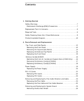
Workstation 8 Product Exploded Diagram 10 2. Parts Removal and Replacement Top, Front, and Side Panels 12 Removing the Front Panel 12 Removing the Top and Side Panels 14 Replacing the Side and Top Panels 15 Replacing the Front Panel 15 Memory Card(s) DIMMS 16 Removing the Front Air Guides - HP Visualize J5000 | hp Visualize J5000, J7000 workstations parts removal and re - Page 4
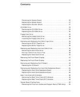
Removing the Real Time Clock (RTC) Module 48 Replacing the Real Time Clock (RTC) Module 49 System Board Cooling Fans 50 Removing the Front Air Guides and Support Bars (J7000 Only) . . . 50 4 - HP Visualize J5000 | hp Visualize J5000, J7000 workstations parts removal and re - Page 5
Contents Removing the System Board Cooling Fans 52 Replacing the System Board Cooling Fan 52 3. Wrapping Up Verifying System Operations 55 Returning the Defective Exchange Assembly 55 5 - HP Visualize J5000 | hp Visualize J5000, J7000 workstations parts removal and re - Page 6
Contents 6 - HP Visualize J5000 | hp Visualize J5000, J7000 workstations parts removal and re - Page 7
, such as a tabletop or workbench. NOTE Installing the recommended HP replacement part in your J Class workstation does not affect the regulatory and safety classifications or approvals listed in the original owner's guide. Electrostatic Discharge (ESD) Precautions To prevent damage to the J Class - HP Visualize J5000 | hp Visualize J5000, J7000 workstations parts removal and re - Page 8
Part • Part Number: A3024-80004, Electrostatic Discharge (ESD) Materials • Removal/Replacement Guide If you are missing any part or any documentation, please call your designated service the rear panel to power down the workstation. This power down method may hang the operating system in an unrecoverable - HP Visualize J5000 | hp Visualize J5000, J7000 workstations parts removal and re - Page 9
. This ensures that all programs are terminated and all data is saved before switching the power off. Power off the workstation by simply pressing the power switch on the front panel of the workstation. Also, power off the monitor and any attached peripheral devices. 2. After 30 seconds unplug the - HP Visualize J5000 | hp Visualize J5000, J7000 workstations parts removal and re - Page 10
for a basic parts overview of the J Class workstation. Top panel Flex cable retainer Flex cable DC/DC converter units and tie downs for J7000 Left side panel DDS-3/floppy EMI cover Chassis Right side panel I/O board Bus bar shield CD EMI cover PCI retainer clip J5000 - HP Visualize J5000 | hp Visualize J5000, J7000 workstations parts removal and re - Page 11
2 Parts Removal and Replacement This chapter describes how to remove and replace the various components in the J Class workstations. 11 - HP Visualize J5000 | hp Visualize J5000, J7000 workstations parts removal and re - Page 12
Parts Removal and Replacement Top, Front, and Side Panels Top, Front, and Side Panels This section describes how to remove and replace the top, front, and side panels. Removing the Front Panel 1. Power down your workstation as described in "Getting Started." If locked, unlock the door on the front - HP Visualize J5000 | hp Visualize J5000, J7000 workstations parts removal and re - Page 13
Figure 2-2. Front Panel Removed Parts Removal and Replacement Top, Front, and Side Panels Panel Hinge Holes Panel-Detach Screw Holes Chapter 2 13 - HP Visualize J5000 | hp Visualize J5000, J7000 workstations parts removal and re - Page 14
Parts Removal and Replacement Top, Front, and Side Panels Removing the Top and Side Panels 1. Facing the back of the workstation, remove the T-15 Torx thumbscrew located in each top corner of the back of the workstation. The upper left one (when facing the back of the workstation) is the power - HP Visualize J5000 | hp Visualize J5000, J7000 workstations parts removal and re - Page 15
and Top Panels Figure 2-4. Back View of the Workstation Top panel Parts Removal and Replacement Top, Front, and Side Panels the two T-15 Torx thumbscrews located in the upper corners in the back of the workstation. Because the left screw engages the power supply, it is important to tighten it suf - HP Visualize J5000 | hp Visualize J5000, J7000 workstations parts removal and re - Page 16
Parts Removal and Replacement Memory Card(s) DIMMS Memory Card(s) DIMMS This components.. Removing the Front Air Guides and Support Bars (J7000 Only) Figure 2-5. J7000's Open Left Side Before Removing Air Guide Support Bar Front Air Guide Four T-15 Torx Screws Support Bar 1. Remove the four T- - HP Visualize J5000 | hp Visualize J5000, J7000 workstations parts removal and re - Page 17
Torx screws. Remove the T-15 Torx screws that secure the bar to the rear air guide. Remove the T-15 Torx screws that secure the bars to the back of the workstation. As you swing out each support bar, the tab end will come out of the slot on the fan wall. Removing the - HP Visualize J5000 | hp Visualize J5000, J7000 workstations parts removal and re - Page 18
Parts Removal and Replacement Memory Card(s) DIMMS Figure 2-7. Removing a DIMM Ejector rmly and evenly push down on each side to lock it into place. The ejector tabs will angle upward. 3. Visually inspect and confirm the connection between the memory card and the system board. 4. Repeat steps 1 and 2 - HP Visualize J5000 | hp Visualize J5000, J7000 workstations parts removal and re - Page 19
Parts Removal and Replacement Power Supply Power Supply This section describes how to remove and replace the Power Supply. NOTE Prior to removing the Power Supply, - HP Visualize J5000 | hp Visualize J5000, J7000 workstations parts removal and re - Page 20
Parts Removal and Replacement Power Supply 4. Remove the two T-15 Torx guide rails and slide it into the I/O board connectors. Alternately tighten the two jack screws (in the upper corners of the power supply). Take care to align the right-side jack screw to the threads in the back of the workstation - HP Visualize J5000 | hp Visualize J5000, J7000 workstations parts removal and re - Page 21
Figure 2-10. Installing the Power Supply, Steps 1-2 Parts Removal and Replacement Power Supply Step 1: Replace Jack Screws Step 2: Replace T-15 Torx Screws 2. Replace the two T-15 Torx screws in the back of the workstation and the one T-15 Torx screw in the lower left corner of the power supply - HP Visualize J5000 | hp Visualize J5000, J7000 workstations parts removal and re - Page 22
Parts Removal and plates 2. Grasp the edges of a PCI card and slide it along the guide rails toward you. It may take some strength to pull the card out the PCI card is stuck, look at the slots from the back of the workstation; the filler plate of the PCI card may be causing the obstruction 3. - HP Visualize J5000 | hp Visualize J5000, J7000 workstations parts removal and re - Page 23
slide the card into the slot on the I/O board. Visually inspect and confirm the connection between the PCI card(s) and the I/O board. NOTE If the PCI card will not slide in, look at the slots from the back of the workstation. Protrusions on the face plate of the PCI card may - HP Visualize J5000 | hp Visualize J5000, J7000 workstations parts removal and re - Page 24
Parts Removal and Replacement Removing and Replacing the Flex Cable Retainer and Cable Removing and Replacing the Flex Cable Retainer and Cable This section describes how - HP Visualize J5000 | hp Visualize J5000, J7000 workstations parts removal and re - Page 25
Parts Removal and Replacement Removing and Replacing the Flex Cable Retainer and Cable Replacing the Flex Cable and Flex Cable Retainer Figure 2-17. Attaching the Flex - HP Visualize J5000 | hp Visualize J5000, J7000 workstations parts removal and re - Page 26
Parts Removal and Replacement Removing and Replacing the System Board Removing and , make sure your static-grounding strap is securely attached to your wrist and to the bare metal on the workstation. Removing the Bus Bar Shield 1. Remove the bus bar shield by pulling outward on its latch, and then - HP Visualize J5000 | hp Visualize J5000, J7000 workstations parts removal and re - Page 27
System Board T-15 T- Torx Screws Parts Removal and Replacement Removing and Replacing the System Board boar tray System Board Handle 2. Remove the three T-15 Torx screws at the back of the workstation that secure the system board tray to the rear wall of the workstation. 3. Grasp the system-board - HP Visualize J5000 | hp Visualize J5000, J7000 workstations parts removal and re - Page 28
Parts Removal and Replacement Removing and Replacing the System Board Figure 2-20. Replace the Bus Bar Shield Step 1: Replace the Bus bar Screws Step 2: Replace the Bus bar Shield 2. Replace the bus bar shield as shown above. 28 Chapter 2 - HP Visualize J5000 | hp Visualize J5000, J7000 workstations parts removal and re - Page 29
Parts Removal and Replacement CD ROM Drive CD ROM Drive This section describes how to CD ROM Drive 1. Remove the two T-15 Torx screws securing the CD ROM drive to the front panel of the workstation chassis. Figure 2-21. CD ROM Drive in Place T-15 Torx Screw T-15 Torx Screw 2. Remove the thin, - HP Visualize J5000 | hp Visualize J5000, J7000 workstations parts removal and re - Page 30
Parts Removal and Replacement CD ROM Drive Figure 2-22. Removing the EMI Cover CD Drive's EMI Cover 3. Slide the CD ROM drive out about halfway and - HP Visualize J5000 | hp Visualize J5000, J7000 workstations parts removal and re - Page 31
Figure 2-24. Attaching CD ROM Drive Cables Power Cable Data Cable Audio Cable Parts Removal and Replacement CD ROM Drive 3. From the front of the workstation, carefully push the CD ROM drive/tray assembly flush against the front panel, taking care not to pinch any cables. 4. Insert and tighten the - HP Visualize J5000 | hp Visualize J5000, J7000 workstations parts removal and re - Page 32
Parts Removal and Replacement CD ROM Drive Figure 2-26. Replacing the EMI Cover CD Drive's EMI Cover 32 Chapter 2 - HP Visualize J5000 | hp Visualize J5000, J7000 workstations parts removal and re - Page 33
Parts Removal and Replacement Floppy Disk Drive Floppy Disk Drive This section describes Drive 1. Remove the two T-15 Torx screws securing the Floppy Disk drive to the front panel of the workstation. Figure 2-27. Removing the Torx Screws T-15 Torx Screw T-15 Torx Screw 2. Remove the thin, metal - HP Visualize J5000 | hp Visualize J5000, J7000 workstations parts removal and re - Page 34
Parts Removal and Replacement Floppy Disk Drive 3. Gently slide the floppy disk floppy disk drive carrier assembly about halfway into the floppy disk drive bay. 2. From the front of the workstation, push the floppy disk drive carrier assembly into the drive bay so that the assembly rests flush against the - HP Visualize J5000 | hp Visualize J5000, J7000 workstations parts removal and re - Page 35
Parts Removal and Replacement Removing and Replacing the DDS-3 Tape Drive Removing and Drive 1. Remove the two T-15 Torx screws securing the DDS-3 tape drive to the front panel of the workstation. (See ) Figure 2-30. Removing the Torx Screws T-15 Torx Screw T-15 Torx Screw 2. Remove the thin - HP Visualize J5000 | hp Visualize J5000, J7000 workstations parts removal and re - Page 36
Parts Removal and Replacement Removing and Replacing the DDS-3 Tape Drive 3. Gently and gently slide the DDS-3 drive carrier halfway into the tape drive bay. 2. From the front of the workstation, push the DDS-3 drive carrier assembly into the drive bay so that the assembly rests flush against the - HP Visualize J5000 | hp Visualize J5000, J7000 workstations parts removal and re - Page 37
Parts Removal and Replacement Removing and Replacing the DDS-3 Tape Drive 3. Insert and tighten the two T-15 Torx screws to secure the DDS-3 tape drive to the front panel. 4. Replace the EMI cover. Chapter 2 37 - HP Visualize J5000 | hp Visualize J5000, J7000 workstations parts removal and re - Page 38
Parts 2. Carefully slide the hard disk drive out of the chassis guide rails and set it aside. Support the weight of the hard drive as it slides free of its tray before you can slide the disk drive and tray assembly into the workstation. 1. Unpack the new disk drive. Never let it drop onto the floor - HP Visualize J5000 | hp Visualize J5000, J7000 workstations parts removal and re - Page 39
Parts Removal and Replacement Removing and Replacing the Hard Disk Drive CAUTION A drop of of gees), which may damage the device. 2. Refer to the hard disk drive you just removed from the workstation. Remove the four screws securing the drive to the tray, and pull the drive straight up out of the - HP Visualize J5000 | hp Visualize J5000, J7000 workstations parts removal and re - Page 40
Parts Removal and Replacement Removing and Replacing the Hard Disk Drive Replacing the Hard Disk Drives Figure 2-36. Details of Hard Disk Drive and Tray Release - HP Visualize J5000 | hp Visualize J5000, J7000 workstations parts removal and re - Page 41
Removing the Front-Panel Display Figure 2-38. Front Panel Display T-15 Torx Screw Power Switch Parts Removal and Replacement Removing the Front-Panel Display 25-pin Connector T-15 Torx Screw Front-Panel Display Release Tab 1. Remove the two T-15 Torx screws - HP Visualize J5000 | hp Visualize J5000, J7000 workstations parts removal and re - Page 42
Parts Removal and Replacement Replacing the Front-Panel Display Replacing the Front-Panel Display 1. Connect the chassis hooks on the left side of the front-panel - HP Visualize J5000 | hp Visualize J5000, J7000 workstations parts removal and re - Page 43
Parts Removal and Replacement Removing and Replacing the I/O Board Removing and Replacing Board Removing the I/O Board 1. Remove the cables from the USB Clip from the back of the Workstation. Figure 2-41. Opening the USB Clip Keyboard and Mouse connectors. Insert a fingernail under the locking - HP Visualize J5000 | hp Visualize J5000, J7000 workstations parts removal and re - Page 44
Parts Removal and Replacement Removing and Replacing the I/O Board Figure 2-42. Back View of the Workstation T-15 Torx Screws 4. Facing the opened workstation, move any cables away from the I/O board. CAUTION To avoid damaging system components with electrostatic discharge (static electricity), - HP Visualize J5000 | hp Visualize J5000, J7000 workstations parts removal and re - Page 45
Parts Removal and Replacement Removing and Replacing the Hard Disk Backplane Board Removing and Replacing the Hard Disk Backplane Board This section describes how to remove - HP Visualize J5000 | hp Visualize J5000, J7000 workstations parts removal and re - Page 46
Parts Removal and Replacement Removing and Replacing the Hard Disk Backplane Board Replacing the Hard Disk Backplane Board Figure 2-43. Hard Disk Backplane Board Hard-Disk - HP Visualize J5000 | hp Visualize J5000, J7000 workstations parts removal and re - Page 47
Parts Removal and Replacement Removing and Replacing the Hard Disk Backplane Board 2. Insert and tighten the four T-15 screws. 3. Connect the two cables: • Push the backplane - HP Visualize J5000 | hp Visualize J5000, J7000 workstations parts removal and re - Page 48
Parts Removal and Replacement Real Time Clock (RTC) Module Real Time Clock (RTC) Module This section describes how to remove and replace and may require a firm grip to remove it. CAUTION Dispose of the Real Time Clock (RTC) Module according to the manufacturer's instructions. 48 Chapter 2 - HP Visualize J5000 | hp Visualize J5000, J7000 workstations parts removal and re - Page 49
Replacing the Real Time Clock (RTC) Module Parts Removal and Replacement Real Time Clock (RTC) Module CAUTION Explosion may result if the RTC Module is incorrectly installed. Polarity dots must be aligned. 1. Remove - HP Visualize J5000 | hp Visualize J5000, J7000 workstations parts removal and re - Page 50
Parts Removal and Replacement System Board Cooling Fans System Board Cooling Fans components. Removing the Front Air Guides and Support Bars (J7000 Only) Figure 2-45. J7000's Open Left Side Before Removing Air Guide Support Bar Front Air Guide Four T-15 Torx Screws Support Bar 1. Remove the four - HP Visualize J5000 | hp Visualize J5000, J7000 workstations parts removal and re - Page 51
T-15 Torx screws. Remove the T-15 Torx screws that secure the bar to the rear air guide. Remove the T-15 Torx screws that secure the bars to the back of the workstation. As you swing out each support bar, the tab end will come out of the slot on the fan wall. Chapter - HP Visualize J5000 | hp Visualize J5000, J7000 workstations parts removal and re - Page 52
the flat part of a screwdriver, press against the pointed end of the rivet and push the rivet completely out, toward the back of the workstation. (If the 4. Remove the fan by pushing it out toward the front of the workstation. Replacing the System Board Cooling Fan NOTE When replacing the fan, use - HP Visualize J5000 | hp Visualize J5000, J7000 workstations parts removal and re - Page 53
Parts Removal and Replacement System Board Cooling Fans 1. Position the fan so that the "flow arrow" points to the back of the workstation. 2. Locate the cable guide slot on the system board fan wall. Align the fan with the slot. Thread the cable through this slot so that it can be connected - HP Visualize J5000 | hp Visualize J5000, J7000 workstations parts removal and re - Page 54
Parts Removal and Replacement System Board Cooling Fans 54 Chapter 2 - HP Visualize J5000 | hp Visualize J5000, J7000 workstations parts removal and re - Page 55
need to use specific HP-UX commands and utilities to reconfigure the workstation to recognize the replacement part(s). Verifying System Operations To verify up, refer to the Troubleshooting chapter of the J Class Owner's Guide. If you have any questions, suggestions, or problems with our hardware or - HP Visualize J5000 | hp Visualize J5000, J7000 workstations parts removal and re - Page 56
Wrapping Up Verifying System Operations 56 Chapter 3
-
 1
1 -
 2
2 -
 3
3 -
 4
4 -
 5
5 -
 6
6 -
 7
7 -
8
-
9
-
10
-
11
-
12
-
13
-
14
-
15
-
16
-
17
-
18
-
19
-
20
-
21
-
22
-
23
-
24
-
25
-
26
-
27
-
28
-
29
-
30
-
31
-
32
-
33
-
34
-
35
-
36
-
37
-
38
-
39
-
40
-
41
-
42
-
43
-
44
-
45
-
46
-
47
-
48
-
49
-
50
-
51
-
52
-
53
-
54
-
55
-
56
 |
 |

HP V
ISUALIZE
J Class UNIX
®
Workstations
Parts
Removal/Replacement Guide
Manufacturing Part Number: A4978-90051
Edition E0100
© Copyright 1999 by Hewlett-Packard