HP Z210 HP Workstations - CRU Dataport DX115 kit installation
HP Z210 Manual
 |
View all HP Z210 manuals
Add to My Manuals
Save this manual to your list of manuals |
HP Z210 manual content summary:
- HP Z210 | HP Workstations - CRU Dataport DX115 kit installation - Page 1
unit (case, drive carrier, and lock key) ● Installation document ● SATA or SAS cable ● Five M3 screws ● Five 6-32 screw ● Tape label Before you begin To view QuickSpecs and determine the compatibility of this product with your HP computer, see http://www.hp.com/go/productbulletin. ENWW © 2006-2010 - HP Z210 | HP Workstations - CRU Dataport DX115 kit installation - Page 2
power from the equipment by unplugging the power cord from the electrical outlet. WARNING! To reduce the risk of serious injury, read the Safety & Comfort Guide. It describes proper computer setup, posture, health, and work habits for computer NOTE: HP accessories are for use in HP computer products. - HP Z210 | HP Workstations - CRU Dataport DX115 kit installation - Page 3
1. If you need help preparing the computer for this installation, consult the removal and replacement procedures in the service guide for your computer at http://www.hp.com/support/ manuals. 2. Power down the computer, and then disconnect the power cord. 3. Power down all external devices, and then - HP Z210 | HP Workstations - CRU Dataport DX115 kit installation - Page 4
Figure 1 Removing the SAS to SATA adapter 4 CRU Dataport DX115 kit installation ENWW - HP Z210 | HP Workstations - CRU Dataport DX115 kit installation - Page 5
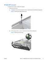
HP Z200 SFF computer To install a DX115 case in a Z200 SFF computer: 1. Remove the front bezel: a. If necessary, remove the bezel security screw, located beside the middle bezel release tab. Figure 2 Removing the bezel security screw b. Lift the release tabs (1), and then rotate the front bezel off - HP Z210 | HP Workstations - CRU Dataport DX115 kit installation - Page 6
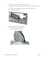
2. If necessary, remove the optical disk drive blank from the bezel: a. On the inside of the bezel, push the two retaining tabs toward the outer edge of the bezel (1) b. Slide the bezel blank back away from the bezel and to the left to remove it (2). Figure 4 Removing the bezel blank 3. If an - HP Z210 | HP Workstations - CRU Dataport DX115 kit installation - Page 7
b. Disconnect the power cable (1) and data cable (2) from the rear of the optical drive. Figure 6 Removing the cables c. Rotate the drive cage back down to its normal position. - HP Z210 | HP Workstations - CRU Dataport DX115 kit installation - Page 8
screw 5. Install four (supplied) M3 x 5mm screws (black) in the lower four mounting holes of the DX115 case. Figure 9 Installing the guide screws 6. Position the guide screws on the drive into the J-slots in the drive bay. Then slide the drive toward the front of the computer until it locks into - HP Z210 | HP Workstations - CRU Dataport DX115 kit installation - Page 9
cage up 8. If the cables are not already routed and attached to the system board: a. Connect the SATA data cable to the system board connector labeled SATA1. b. Route the data cable through the cable guides to keep the data cable from being pinched by the drive cage when raising or lowering it - HP Z210 | HP Workstations - CRU Dataport DX115 kit installation - Page 10
you rotate the drive cage. The cage may pinch the cables and damage them if they are not routed correctly. HP Z200, Z400, and HP xw4000 computers 1. Remove the front bezel from the computer to access the optical bays. a. Lift the tab (1). b. Pivot the bezel to disengage the lower edge (2). Figure 14 - HP Z210 | HP Workstations - CRU Dataport DX115 kit installation - Page 11
at the side of the DX115 case. Figure 15 Removing the shipping screw 3. Install four (supplied) M3 x 5mm screws (black) in the lower four mounting holes. Figure 16 Installing the mounting screws 4. Lift the green release lever for the optical bay and slide the DX115 unit into the bay until it is - HP Z210 | HP Workstations - CRU Dataport DX115 kit installation - Page 12
(supplied) M3 x 5mm screw (black) for each DX115 unit for shipping support as shown. CAUTION: Failure to install the shipping screw might result in damage to the removable hard drive system. Figure 18 Installing the shipping support screw HP xw6200, xw6400, and xw6600 computers 1. Remove the front - HP Z210 | HP Workstations - CRU Dataport DX115 kit installation - Page 13
the removable hard drive system. Figure 21 Installing the shipping support screw HP Z600 and Z800 computers 1. For HP Z800 computers: ● Remove the airflow guide to enable access to the optical bays. ● Remove the card support to enable access to the system board connectors. 2. Remove and discard the - HP Z210 | HP Workstations - CRU Dataport DX115 kit installation - Page 14
4. Install one (supplied) M3 x 5mm screw (black) for each DX115 unit for shipping support. CAUTION: Failure to install the shipping screw might result in damage to the removable hard drive system. Figure 24 Installing the shipping support screw 14 CRU Dataport DX115 kit installation ENWW - HP Z210 | HP Workstations - CRU Dataport DX115 kit installation - Page 15
HP xw8000 and xw9000 computers 1. Remove the front bezel from the computer. See Figure 14 Removing the front bezel on page 10. 2. Remove and discard the counter-sunk shipping screw at the side of the DX115 case. Figure 25 Removing the shipping screw 3. Lift and hold the drive release latch at the - HP Z210 | HP Workstations - CRU Dataport DX115 kit installation - Page 16
The CRU Dataport DX115 User's Guide for SATA or SAS removable drive enclosures workstation is booted and then powering the drive via the power switch on the enclosure. Microsoft Windows XP and Windows Vista do not support this action. NOTE: You do not have to remove the DX115 case from the computer - HP Z210 | HP Workstations - CRU Dataport DX115 kit installation - Page 17
way to the rear end of the carrier so that the power and data connectors mate with the carrier adapter. Figure 30 Installing the cover with the slot on the rear of the carrier (1) and then rotating the front of the cover onto the carrier (2). Figure 31 Replacing the cover 7. Replace the locking - HP Z210 | HP Workstations - CRU Dataport DX115 kit installation - Page 18
guide describes a procedure for inserting or removing the carrier (with drive) while the workstation is booted and then powering the drive via the power switch on the enclosure. Microsoft Windows XP and Windows Vista do not support this action. 1. After the drive case is installed in the computer - HP Z210 | HP Workstations - CRU Dataport DX115 kit installation - Page 19
the data cable to the appropriate connector on the system board or controller card. ● Connect SATA drives to SATA ports, and SAS drives to SAS ports, starting with the lowestnumbered available port. ● For HP Z400 and Z600 computers, the blind-mate cables for the internal hard drive bays may require
-
 1
1 -
 2
2 -
 3
3 -
 4
4 -
 5
5 -
 6
6 -
 7
7 -
8
-
9
-
10
-
11
-
12
-
13
-
14
-
15
-
16
-
17
-
18
-
19
 |
 |

CRU Dataport DX115 kit installation
Introduction
This document describes how to install the CRU Dataport DX115® removable media kit in an HP
computer. The DX115 kit lets you install removable media in your computer.
Kit contents
●
Warranty information
●
DX115 unit (case, drive carrier, and lock key)
●
Installation document
●
SATA or SAS cable
●
Five M3 screws
●
Five 6-32 screw
●
Tape label
Before you begin
To view
QuickSpecs
and determine the compatibility of this product with your HP computer, see
go/productbulletin
.
© 2006–2010 Hewlett-Packard Development Company, L.P. Microsoft, Windows,
and Windows Vista are U.S. registered trademarks of Microsoft Corporation.
Printed in the U.S.
ENWW
Introduction
1