Hitachi 50HDT50 Owners Guide - Page 18
Connecting External Audio/video Devices
 |
View all Hitachi 50HDT50 manuals
Add to My Manuals
Save this manual to your list of manuals |
Page 18 highlights
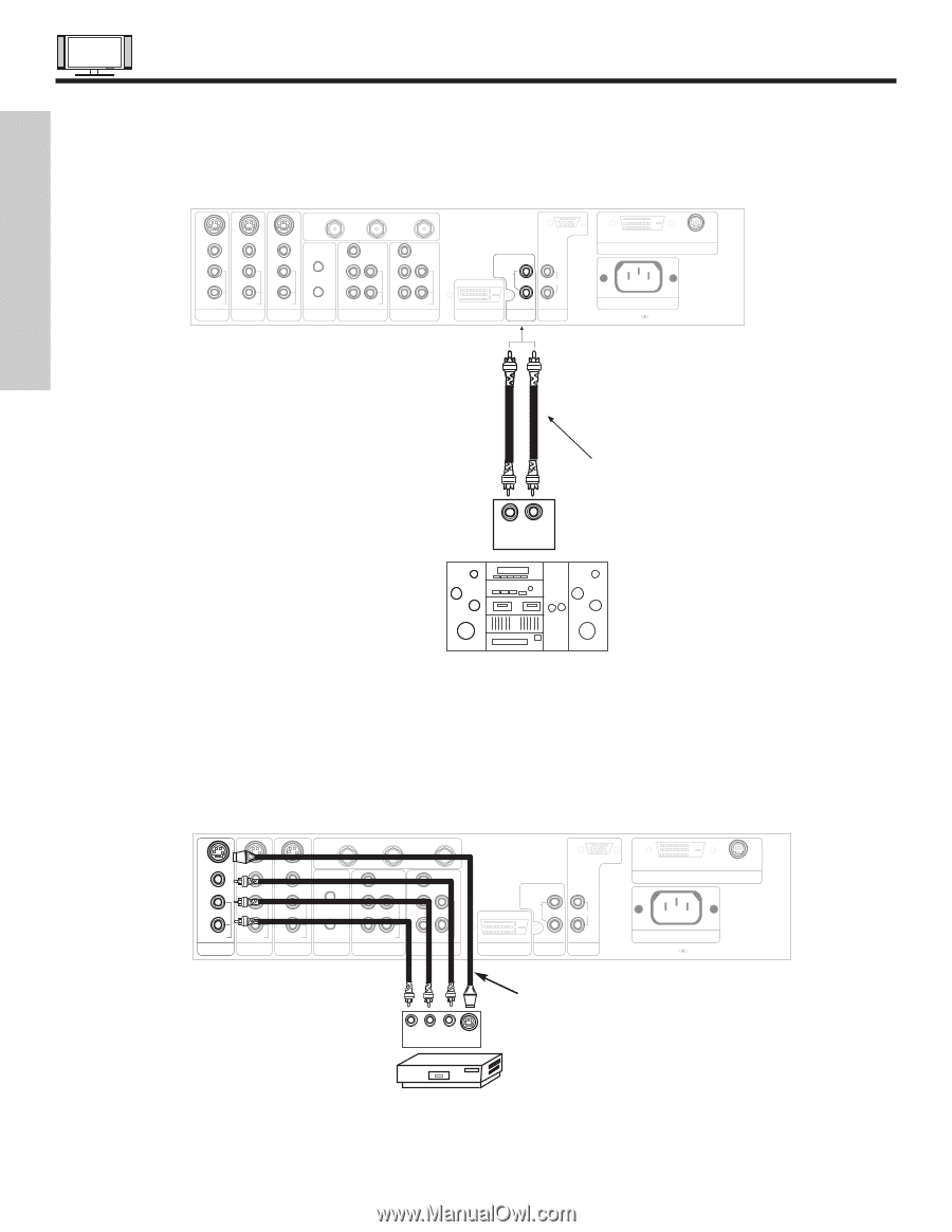
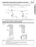
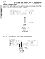
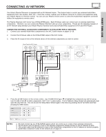
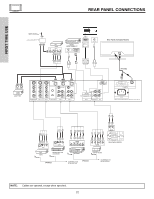
FIRST TIME USE CONNECTING EXTERNAL AUDIO/VIDEO DEVICES CONNECTING EXTERNAL AUDIO AMPLIFIER To monitor the audio level of the Plasma TV to an external audio amplifier, connect the system as shown below. The "AUDIO OUT" from the AVC center is a fixed output. The Volume of the amplifier is controlled by the amplifier, not by the Plasma Television. The AUDIO OUT terminal outputs all audio sources (ANT A/B, INPUT 1~5 and RGB). Rear Panel of AVC Center ANT B TO CONVERTER ANT A S-VIDEO S-VIDEO VIDEO VIDEO L L/(MONO) R AUDIO MONITOR OUT R AUDIO INPUT 4 S-VIDEO VIDEO Y/VIDEO Y L/(MONO) PB L/(MONO) PB L/(MONO) R AUDIO INPUT 3 IR BLASTER PR R AUDIO INPUT 2 PR R AUDIO INPUT 1 ANALOG INPUT L AUDIO DVI-HDTV L/(MONO) AUDIO Please use HITACHI specified cable. TO MONITOR INPUT 1 R R AUDIO OUT RGB AC IN TruBass SRS and symbol are trademarks of SRS Labs, Inc. RL INPUT To Audio Input Terminal of External Amplifier Stereo System Amplifier The MONITOR OUT terminal outputs video and audio of ANT A/B and INPUT2~5 only. It does not output component video, DVIHDTV or RGB. If a component device is input to INPUT2, no monitor out is available for this output. Rear Panel of AVC Center ANT B TO CONVERTER ANT A S-VIDEO S-VIDEO VIDEO L VIDEO L/(MONO) R AUDIO MONITOR OUT R AUDIO INPUT 4 S-VIDEO VIDEO Y/VIDEO Y L/(MONO) PB L/(MONO) PB L/(MONO) R AUDIO INPUT 3 IR BLASTER PR R AUDIO INPUT 2 PR R AUDIO INPUT 1 ANALOG INPUT L AUDIO DVI-HDTV L/(MONO) AUDIO Please use HITACHI specified cable. TO MONITOR INPUT 1 R R AUDIO OUT RGB AC IN TruBass SRS and symbol are trademarks of SRS Labs, Inc. R L V S-VIDEO INPUT Optional, See page 23 VCR or other external components 18
-
 1
1 -
2
-
3
-
4
-
5
-
6
-
7
-
8
-
9
-
10
-
11
-
12
-
 13
13 -
 14
14 -
 15
15 -
 16
16 -
 17
17 -
 18
18 -
 19
19 -
 20
20 -
 21
21 -
 22
22 -
 23
23 -
24
-
25
-
26
-
27
-
28
-
29
-
30
-
31
-
32
-
33
-
34
-
35
-
36
-
37
-
38
-
39
-
40
-
41
-
42
-
43
-
44
-
45
-
46
-
47
-
48
-
49
-
50
-
51
-
52
-
53
-
54
-
55
-
56
-
57
-
58
-
59
-
60
-
61
-
62
-
63
-
64
-
65
-
66
-
67
-
68
-
69
-
70
-
71
-
72
-
73
-
74
-
75
-
76
-
77
-
78
-
79
-
80
-
81
-
82
-
83
-
84
 |
 |