Hitachi 7K320 Specifications
Hitachi 7K320 - Travelstar Mobile Hard Drive Manual
 |
UPC - 890552647200
View all Hitachi 7K320 manuals
Add to My Manuals
Save this manual to your list of manuals |
Hitachi 7K320 manual content summary:
- Hitachi 7K320 | Specifications - Page 1
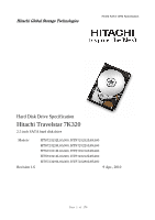
Global Storage Technologies 7K320 SATA OEM Specification Hard Disk Drive Specification Hitachi Travelstar 7K320 2.5 inch SATA hard disk drive Models: Revision 1.6 HTS723232L9A360, HTS723232L9SA60 HTS723225L9A360, HTS723225L9SA60 HTS723216L9A360, HTS723216L9SA60 HTS723212L9A360, HTS723212L9SA60 - Hitachi 7K320 | Specifications - Page 2
(Revision 1.6) (09 April 2010) 7K320 SATA OEM Specification The following paragraph does not apply to the United Kingdom or any country where such provisions are inconsistent with local law: HITACHI GLOBAL STORAGE TECHNOLOGIES PROVIDES THIS PUBLICATION "AS IS" WITHOUT WARRANTY OF ANY KIND, EITHER - Hitachi 7K320 | Specifications - Page 3
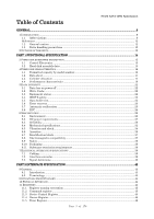
OF THE DRIVE...13 PART 1 FUNCTIONAL SPECIFICATION 14 3 FIXED DISK SUBSYSTEM DESCRIPTION 15 3.1 Control Electronics ...15 3.2 Head disk assembly data ...15 4 FIXED DISK CHARACTERISTICS...16 4.1 Formatted capacity by model number 16 4.2 Data sheet ...17 4.3 Cylinder allocation ...17 4.4 Performance - Hitachi 7K320 | Specifications - Page 4
7K320 SATA OEM Specification 11.6 Features Register ...46 11.7 LBA High Register ...47 11.8 LBA Low Max Address (F8h 118 14.21 Read Native Max Address Ext (27h 119 14.22 Read Sector(s) (20h/21h)...120 14.23 Read Sector(s) Ext (24h)...121 14.24 Read Verify Sector(s) (40h/41h 122 14.25 Read Verify - Hitachi 7K320 | Specifications - Page 5
by model number. 16 Table 2. Data sheet 17 Table 3. Cylinder allocation 17 Table 4. Performance characteristics 18 Table 5. Mechanical positioning performance 19 Table 6. Full stroke seek time 19 Table 7. Single track seek time 19 Table 8. Latency time 19 Table 9. Drive ready time - Hitachi 7K320 | Specifications - Page 6
7K320 SATA OEM Specification Table 17. Random vibration PSD profile breakpoints (operating) 34 Table 18. Swept sine vibration 34 Table 19. Random Vibration SCT Action Code Supported 68 Table 80 Number of cylinders/heads/sectors by models for HTS7232XXL9SA6X / HTS7232XXL9A36X 99 Table 65 Number - Hitachi 7K320 | Specifications - Page 7
80 of 176 7K320 SATA OEM Specification 111 112 113 113 114 115 116 117 118 119 120 121 122 123 124 125 125 126 127 127 129 130 130 132 132 133 134 135 137 139 141 142 143 146 148 149 150 153 153 154 154 155 155 155 157 158 158 159 160 - Hitachi 7K320 | Specifications - Page 8
7K320 SATA OEM Specification Page 8 of 176 - Hitachi 7K320 | Specifications - Page 9
This document describes the specifications of the HITACHI Travelstar 7K320, a 2.5-inch hard disk drive with Serial ATA interface: Drive name Travelstar 7K320-320 Model Number HTS723232L9A360 HTS723232L9SA60 Max data transfer rate (Gbps) 3.0 1.5 Capacity (GB) 320 Height (mm) 9.5 Rotation speed - Hitachi 7K320 | Specifications - Page 10
Esd FCC FRU G Gb GB GND h HDD Hz I ILS imped I/O ISO KB Kbit 000 bits 1 000 000 000 bytes ground hexadecimal hard disk drive hertz Input integrated lead suspension impedance Input/Output International Standards Newton meter number oscillations per minute Page 10 of 176 7K320 SATA OEM Specification - Hitachi 7K320 | Specifications - Page 11
RH RMS RPM RST R/W sec Sect/Trk SELV S.M.A.R.T Trk. TTL UL V VDE W 3-state Output 7K320 SATA OEM Specification Open Drain Programmed Input/Output power on hours population part number peak-to-peak power spectral density radiated electromagnetic susceptibility radio frequency interference - Hitachi 7K320 | Specifications - Page 12
References 7K320 SATA OEM Specification Serial ATA International Organization: Serial ATA Revision 2.6 1.2 General caution Do of the printed circuit board. The drive can be damaged by shock or ESD (Electric Static Discharge). Any damages incurred to the drive after removing it from the shipping - Hitachi 7K320 | Specifications - Page 13
2 Outline of the drive 7K320 SATA OEM Specification ・ 2.5-inch, 9.5-mm Height ・ Perpendicular Recording ・ Formatted capacities of 320GB, 250GB, 160GB, 120GB, and 80GB (512 bytes/sector) ・ SATA Interface conforming to Serial ATA International Organization: Serial ATA Revision 2.6(15-February-2007) - Hitachi 7K320 | Specifications - Page 14
7K320 SATA OEM Specification Part 1 Functional Specification Page 14 of 176 - Hitachi 7K320 | Specifications - Page 15
7K320 SATA OEM Specification 3 Fixed disk subsystem description 3.1 Control Electronics The control electronics works with the only) 3.2 Head disk assembly data The following technologies are used in the drive: Femto Slider Perpendicular recording disk and write head TMR head Integrated lead - Hitachi 7K320 | Specifications - Page 16
Fixed disk characteristics 7K320 SATA OEM Specification 4.1 Formatted capacity by model number Description Physical Layout Bytes per Sector Sectors per Track Number of Heads Number of Disks Logical Layout Number of Sectors Total Logical Data Bytes HTS723232L9A360 HTS723225L9A360 HTS723232L9SA60 - Hitachi 7K320 | Specifications - Page 17
Specification 320GB 250GB 160GB 120GB 80GB Rotational Speed (RPM) Data transfer rates (buffer to/from media) (Mbps) Data transfer rates (Gbit/sec) Recording density (Kbit/mm) (Max) (KBPI) (Max) Track density (Ktrack/mm)(Max) (KTPI)(Max) Areal density (Gbit/sq-mm.- Max) (Gbit/sq-inch - Max) Number - Hitachi 7K320 | Specifications - Page 18
7K320 SATA OEM Specification 4.4 Performance characteristics Drive performance is characterized by the following parameters: Command Overhead Mechanical Positioning Seek Time Latency Data Transfer Speed Buffering Operation (Look ahead/Write Cache) Note: All the - Hitachi 7K320 | Specifications - Page 19
7K320 SATA OEM Specification 4.4.2.1 Average seek time (including settling) Command Type Typical (ms) Read/Write 12 Table 5. Mechanical positioning performance Max. (ms) 18 Typical and Max. are defined throughout the performance specification as follows: Typical Average of the drive - Hitachi 7K320 | Specifications - Page 20
time Condition Power On To Ready Table 9. Drive ready time Typical (sec) 4.0 7K320 SATA OEM Specification Max. (sec) 9.5 Ready The condition in which the drive is able to perform a media access command (for example-read, write) immediately. Power On To Ready This includes the time required - Hitachi 7K320 | Specifications - Page 21
7K320 SATA OEM Specification Operating mode Description Spin-Up Start up time period from spindle stop or power down. Seek Seek operation mode Write Write operation mode Read Read operation mode The device is capable of responding immediately to idle media access requests. All Performance - Hitachi 7K320 | Specifications - Page 22
5 Data integrity 7K320 SATA OEM Specification 5.1 Data loss on power off Data loss will not be caused command Confirm the command's completion. 5.3 Equipment status The equipment status is available to the host system any time the drive is not ready to read, write, or seek. This status normally - Hitachi 7K320 | Specifications - Page 23
7K320 SATA OEM Specification The data buffer is tested at power on reset and when a drive self-test is requested by the host. The test consists of a write/read '00'x and 'ff'x pattern on all buffers. 5.6 Error recovery Errors occurring on the drive fully carried out, a hard error is reported to the - Hitachi 7K320 | Specifications - Page 24
5.8 ECC 7K320 SATA OEM Specification The 10 bit 40 symbol non interleaved ECC processor provides user data verification and correction capability. The first 6 symbol of ECC are 4 check symbols for - Hitachi 7K320 | Specifications - Page 25
60°C at the center of top cover and below 63°C at the center of the drive circuit board assembly. The maximum storage period in the shipping package is one year. Relative Humidity (%) Specification (Environment) 100 90 80 31'C/90% 41'C/95% W etBulb 40'C 70 60 Non Operating W etBulb29.4'C 50 - Hitachi 7K320 | Specifications - Page 26
6.1.3 Radiation noise 7K320 SATA OEM Specification The disk drive shall work without degradation of the soft error rate under the following magnetic flux density limits at the enclosure surface. Frequency (KHz) DC 0 < Frequency =< 60 60 < Frequency = - Hitachi 7K320 | Specifications - Page 27
6.2 DC power requirements 7K320 SATA OEM Specification Connection to the product should be made in a safety extra low voltage (SELV) circuits. The voltage specifications are applied at the power connector of the drive. Item Nominal supply Supply voltage Power supply ripple (0-20 MHz)1 Tolerance 2 - Hitachi 7K320 | Specifications - Page 28
6.2.1 Power consumption efficiency 7K320 SATA OEM Specification Capacity 320GB 250GB 160GB 120GB 80GB Power Consumption Efficiency 0.0025 0.0032 0.0050 0.0067 0.0100 (Watts/GB) Table 15. Power consumption efficiency Note: Power consumption efficiency is calculated as - Hitachi 7K320 | Specifications - Page 29
allowable level specified in the power requirement section. 6.3.4 Service life and usage condition The drive is designed to be used under the following conditions: The drive should be operated within specifications of shock, vibration, temperature, humidity, altitude, and magnetic field. The - Hitachi 7K320 | Specifications - Page 30
6.3.6 Load/unload 7K320 SATA OEM Specification The product supports a minimum of 600,000 normal load/unloads. Load/unload is a functional mechanism of the hard disk drive. It is controlled by the drive micro code. Specifically, unloading of the heads is invoked by the following commands: Standby - Hitachi 7K320 | Specifications - Page 31
Test considerations 7K320 SATA OEM Specification Start/stop testing is classically performed to drive invokes the emergency unload mechanism and subjects the HDD to nontypical mechanical stress. Power cycling testing may be required to test the boot-up function of the system. In this case HItachi - Hitachi 7K320 | Specifications - Page 32
6.4.1 Physical dimensions and weight 7K320 SATA OEM Specification The following figure lists the dimensions for the drive. Model Height (mm) 320/250GB 9.5±0.2 160/120/80GB 9.5±0.2 Table 16. Physical dimensions and weight Width (mm) 69.85±0.25 69.85±0.25 6.4.2 Mounting hole locations - Hitachi 7K320 | Specifications - Page 33
tilted ±5 degrees from these positions. Performance and error rate will stay within specification limits if the drive is operated in the other permissible mounting hardware to mount the drive securely enough to prevent excessive motion or vibration of the drive at seek operation or spindle rotation - Hitachi 7K320 | Specifications - Page 34
and shock 7K320 SATA OEM Specification All vibration and shock measurements in this section are for drives without mounting attachments for systems. The input level shall be applied to the normal drive mounting points. Vibration tests and shock tests are to be conducted by mounting the drive to - Hitachi 7K320 | Specifications - Page 35
6.5.2 Nonoperating vibration 7K320 SATA OEM Specification The disk drive withstands the following vibration levels without any loss or permanent damage. 6.5.2.1 Random vibration The test consists of a random vibration applied in each of three mutually perpendicular axes for a duration of 15 - Hitachi 7K320 | Specifications - Page 36
6.6 Acoustics 6.6.1 Sound power level 7K320 SATA OEM Specification The criteria of A-weighted sound power level are described below. Measurements are to be taken in accordance with ISO 7779. The mean of the sample of 40 drives is to be less than the typical value. Each drive is to be less than the - Hitachi 7K320 | Specifications - Page 37
labels 7K320 SATA OEM Specification The following labels are affixed to every drive: A label which is placed on the top of the head disk assembly containing the statement "Made by Hitachi" or equivalent, part number, EC number, and FRU number. A bar code label which is placed on the disk drive - Hitachi 7K320 | Specifications - Page 38
SATA OEM Specification 6.9 Safety 6.9.1 UL and CSA approval All models of the Travelstar 7K320 are qualified per UL60950-1:2003 6.9.2 IEC compliance All models of the Travelstar 7K320 comply with IEC 60950-1:2001. 6.9.3 German Safety Mark All models of the Travelstar 7K320 are approved by TUV on - Hitachi 7K320 | Specifications - Page 39
7K320 SATA OEM Specification 7 Electrical interface specifications 7.1 Cabling The maximum cable length from the host system to the hard disk drive plus circuit pattern length in the host system shall not exceed 1 meter. 7.2 Interface connector The figure below shows the physical pin location. - Hitachi 7K320 | Specifications - Page 40
and by the host to indicate whether staggered spinup should be used. The signal the drive provides for activity indication is a low-voltage low-current driver. If pin P11 is asserted low the drive shall disable staggered spin-up and immediately initiate spin-up. If pin P11 is not connected - Hitachi 7K320 | Specifications - Page 41
T3 ALIGN primitives T4 Spacing Figure 4. Parameter descriptions Nominal (ns) 106.7 320 106.7 106.7 8. Model name HTS7232ccL9iimb Capacity : cc 320GB is "32", 250GB is "25", 160GB is "16", 120GB is "12", 80GB is "80". Interface : ii For Standard Model A3 SATA 3Gb SA SATA 1.5G Momory - Hitachi 7K320 | Specifications - Page 42
7K320 SATA OEM Specification Part 2 Interface Specification Page 42 of 176 - Hitachi 7K320 | Specifications - Page 43
from Standard" on Serial ATA International Organization : Serial ATA Revision 2.6 dated on 15 February 2007 AT Attachment 8 - ATA/ATAPI Command Set (ATA8-ACS) Revision 3f dated on 11 December 2006 HTS7232XXL9SAXX / HTS7232XXL9A3XX support following functions as Vendor Specific Function. Format - Hitachi 7K320 | Specifications - Page 44
7K320 SATA OEM Specification The device conforms to the referenced specifications Idle mode. This command does not support 80h as the return value. Security Security State SEC1, the drive responds with "Command Abort details, please refer to the Serial ATA Specification. In the following cases, the - Hitachi 7K320 | Specifications - Page 45
7K320 SATA OEM Specification 11.1 Register naming convention This specification uses the same naming conventions for the Command Block Registers as the ATA8-ACS standard. However, the register naming convention is different from that uses in the Serial ATA 2.6 specification. The following table - Hitachi 7K320 | Specifications - Page 46
Bit Definitions SRST (RST) -IEN 7K320 SATA OEM Specification Software Reset. The device is held reset when 4 3 2 1 0 0 HS3 HS2 HS1 HS0 This register contains the device and head numbers. Bit Definitions L HS3,HS2,HS1,HS0 Binary encoded address mode select. When L=0, addressing is - Hitachi 7K320 | Specifications - Page 47
11.7 LBA High Register 7K320 SATA OEM Specification This register contains Bits 16-23. At the the "previous content" contains Bits 32-39. 11.10 Sector Count Register This register contains the number of sectors of data requested to be transferred on a read or write operation between the host and - Hitachi 7K320 | Specifications - Page 48
DRDY (RDY) DF DSC DRQ CORR (COR) IDX ERR 7K320 SATA OEM Specification the Status Register will be returned. Device Ready. RDY=1 indicates that the device is capable of responding to a command. RDY will be set to 0 during - Hitachi 7K320 | Specifications - Page 49
7K320 SATA OEM Specification 12 General Operation Descriptions 12.1 Reset Response There are three types of reset in ATA as follows: Power On Reset (POR) The device executes a series Reverting programmed parameters to default O (*6) (*3) - Number of CHS (set by Initialize Device Parameter) - - Hitachi 7K320 | Specifications - Page 50
7K320 SATA OEM Specification Register Error Sector Count LBA Low LBA Mid LBA High Device Status Alternate Status Table 30 Default Register Values Default Value Diagnostic Code 01h 01h - Hitachi 7K320 | Specifications - Page 51
/Unload 7K320 SATA OEM Specification Load/Unload is a functional mechanism of the HDD. It is controlled by the drive microcode. Specifically, unloading a hard error. Heads possibly land in the data zone instead of landing zone, depending on the design of the HDD. You may then turn off the HDD in - Hitachi 7K320 | Specifications - Page 52
Mode 7K320 SATA OEM Specification All on the disk media. HTS7232XXL9SAXX / HTS7232XXL9A3XX support both Logical CHS Addressing Mode and LBA number of sectors per logical track and the number of heads per logical cylinder. The device then computes the number of logical cylinders available - Hitachi 7K320 | Specifications - Page 53
Immediate command 12.5.1 Power Mode 7K320 SATA OEM Specification Sleep Mode The lowest power consumption Activate the spindle break to stop the spindle motor 5. Wait until spindle motor is stopped 6. Perform post process 12.5.4 Status In the active, idle and standby modes, the device shall have - Hitachi 7K320 | Specifications - Page 54
7K320 SATA OEM Specification After power on the device goes to IDLE mode or STANDBY mode depending on the setting of the Power Up in Standby Feature set 12.6 Advanced Power Management (Adaptive Battery Life Extender 3) Feature This feature provides power saving without performance is supported if - Hitachi 7K320 | Specifications - Page 55
7K320 SATA OEM Specification supported by both Device-initiated interface power management and Host-initiated interface power management. Please refer to the Serial ATA Specification products. 12.8.1 Attributes Attributes are the specific performance or calibration parameters that are used in - Hitachi 7K320 | Specifications - Page 56
Attribute values 7K320 SATA OEM Specification Attribute values are used to represent the relative reliability of individual performance or can prevent unauthorized access to hard disk device even if the device is removed from the computer. New commands are supported for this feature as below - Hitachi 7K320 | Specifications - Page 57
12.9.1 Security mode 7K320 SATA OEM Specification Following security modes are provided. Device Locked mode The device disables media access commands after power on. Media access commands are enabled by either a security - Hitachi 7K320 | Specifications - Page 58
7K320 SATA OEM Specification Figure 5 Initial Setting .1 Operation from POR after User Password is set When Device Lock Function is enabled, the device rejects media access command until a Security Unlock command is successfully completed. Page 58 of 176 - Hitachi 7K320 | Specifications - Page 59
7K320 SATA OEM Specification (*1) refer to Table 35 Command table for device lock operation on Page 61 and Table 36 Command table for device lock operation - continued on Page - Hitachi 7K320 | Specifications - Page 60
7K320 SATA OEM Specification Figure 7 Password Lost .3 Attempt limit for SECURITY UNLOCK command The SECURITY UNLOCK command has an attempt limit. The purpose of this attempt limit is to prevent that someone attempts to unlock the drive by using various passwords many times. The device counts - Hitachi 7K320 | Specifications - Page 61
Features Table 35 Command table for device lock operation 7K320 SATA OEM Specification Device Locked Mode o x o x x x o x x x x o o o o o o x x x o x x o o x x x x o x o o x x o o o o Device Unlock Mode o o o o o o o o o o o o o o o o o o o o o o o o o o o o o o o o o o o o o o o Device Frozen - Hitachi 7K320 | Specifications - Page 62
Uncorrectable Ext Table 36 Command table for device lock operation - continued 7K320 SATA OEM Specification Device Locked Mode x x o o o o o o o o o o o o o o o o o o o o x x x x x x x x x x x Device Unlock Mode o o o o o o o o o o o o o o o o o o o o o o o o o o o o o o o o o Device Frozen Mode - Hitachi 7K320 | Specifications - Page 63
7K320 SATA OEM Specification Address command is issued. Any BIOSes, device drivers, or application software access the HDD as if that is the 528MB device real 528MB device does. 2. Conventional usage without system software support Since the HDD works as 528MB device, there is no special care to - Hitachi 7K320 | Specifications - Page 64
7K320 SATA OEM Specification 12.10.2 Set Max security extension commands The Set Max Set Password command allows the host to define the password to be used during the - Hitachi 7K320 | Specifications - Page 65
7K320 SATA OEM Specification Figure 8 Set Max security mode transition 12.11 Seek Overlap HTS7232XXL9SAXX / HTS7232XXL9A3XX provide accurate seek time measurement method. The seek command is usually used to measure the device seek time by accumulating execution time for a number of seek commands. - Hitachi 7K320 | Specifications - Page 66
and the auto reallocation fails. If the number of available spare sectors reaches 16 sectors, the write cache function will be disabled automatically. Non recovered read errors When a read operation fails after defined ERP is fully carried out, a hard error is reported to the host system. This - Hitachi 7K320 | Specifications - Page 67
7K320 SATA OEM Specification 28-bit and 48-bit commands may be intermixed. Support of the 48-bit Address feature set is indicated in reset it has issued. In Serial ATA, COMRESET is equivalent to hard reset and a non-commanded COMRESET software settings without legacy driver knowledge, the software - Hitachi 7K320 | Specifications - Page 68
Defaults Block size 12.16 Native Command Queuing Native Command Queuing feature (Read / Write FPDMA Queued commands) is supported. Please refer to the Serial ATA II Specification about Native Command Queuing. The host shall not issue a legacy ATA command while a native queued command is outstanding - Hitachi 7K320 | Specifications - Page 69
7K320 (SATA) OEM Specification The commands are grouped into different classes according to the protocols followed for command execution. The command classes with their associated protocols are defined below. Please refer to Serial there may be a problem, such as a of data is available in the Status - Hitachi 7K320 | Specifications - Page 70
7K320 (SATA) OEM Specification Security Set Password Security Unlock Set Max Set Password Set Max Unlock S.M.A.R.T Write Log Sector Write Buffer Write Log Ext Write Multiple Write Multiple Ext - Hitachi 7K320 | Specifications - Page 71
these commands involves no data transfer. 7K320 (SATA) OEM Specification 13.4 DMA Data Transfer Commands These performance multi-tasking operating systems to eliminate processor overhead associated with PIO transfers. Refer Functional Specification Serial ATA revision 2.6". Page 71 of 176 - Hitachi 7K320 | Specifications - Page 72
2 Security Erase Unit 3 Security Freeze Lock 2 Security Set Password 2 Security Unlock 3 Seek 3 Sense Condition 3 Set Features Table 40 Command set Page 72 of 176 7K320 (SATA) OEM Specification Code (Hex) E5 98 B1 B1 B1 B1 92 90 E7 EA 50 F7 EC E3 97 E1 95 E1 91 E4 C8 C9 - Hitachi 7K320 | Specifications - Page 73
Multiple FUA Ext 2 Write Sector(s) 2 Write Sector(s) 2 Write Sector(s) Ext 3 Write Uncorrectable Ext 7K320 (SATA) OEM Specification Code (Hex) 7 6 5 4 3 2 1 0 F9 1 1 1 1 1 0 0 1 37 0 0 1 1 0 1 1 1 F9 1 1 1 1 1 0 0 1 F9 1 1 1 1 1 0 0 1 F9 1 1 1 1 1 0 0 1 F9 1 1 1 1 1 0 0 1 C6 1 1 0 0 0 1 1 0 E6 - Hitachi 7K320 | Specifications - Page 74
Serial Subcommand) 7K320 (SATA) OEM Specification ( supported by each command or feature. The following symbols are used in the command descriptions: Output Registers 0 Indicates that the bit must be set to 0. 1 Indicates that the bit must be set to 1. H Head number. Indicates that the head number - Hitachi 7K320 | Specifications - Page 75
7K320 (SATA) OEM Specification V Valid. Indicates that the bit is part of an output parameter bit is always set to 0. 1 Indicates that the bit is always set to 1. H Head number. Indicates that the head number part of the Device Register is an input parameter and will be set by the device. V Valid - Hitachi 7K320 | Specifications - Page 76
7K320 (SATA) OEM Specification 14.1 Check Power Mode (E5h/98h) Command Block Output Registers The Check Power Mode command will report whether the device is spun up and the media is available for immediate access. Input Parameters From The Device Sector Count The power mode code. The command - Hitachi 7K320 | Specifications - Page 77
7K320 (SATA) OEM Specification 14.2 Device Configuration Overlay (B1h) Command Block Output Registers Register 76543210 Data -------- Feature 1 0 1 0 VVVV Sector Count -------- LBA Low -------- LBA Mid -------- LBA High -------- Device -------- Command 10110001 - Hitachi 7K320 | Specifications - Page 78
7K320 (SATA) OEM Specification 14.2.3 DEVICE CONFIGURATION IDENTIFY (subcommand C2h) The DEVICE of the IDENTIFY DEVICE command response. When the bits in these words are cleared, the device no longer supports the indicated command, mode, or feature set. If a bit is set in the overlay transmitted by - Hitachi 7K320 | Specifications - Page 79
7K320 (SATA) OEM Specification Word Content 0 0002h Data Structure revision 1 Multiword DMA modes supported 15-3 Reserved 2 1 = Multiword DMA mode 2 and below are supported 1 1 = Multiword DMA mode 1 and below are supported 0 1 = Multiword DMA mode 0 is supported 2 Ultra DMA modes - Hitachi 7K320 | Specifications - Page 80
7K320 (SATA) OEM Specification LBA High invalid word location LBA Mid invalid bit location (bits (7:0)) LBA Low invalid mode 06h Protected area is now established 07h DCO is not supported 08h Subcommand code is invalid FFh other reason Table 47 DCO error information definition Page - Hitachi 7K320 | Specifications - Page 81
14.3 Download Microcode (92h) 7K320 (SATA) OEM Specification Command Block Output Registers Register 76543210 alter the device's microcode. The data transferred using the DOWNLOAD MICROCODE commands is vendor specific. All transfers shall be an integer multiple of the sector size. The size of - Hitachi 7K320 | Specifications - Page 82
7K320 (SATA) OEM Specification DOWNLOAD MICROCODE command buffer offset and the previous sector count. The first DOWNLOAD MICROCODE command shall have a buffer offset of zero. The new firmware microcode command for the firmware download the device will perform any device required verification - Hitachi 7K320 | Specifications - Page 83
7K320 (SATA) OEM Specification 14.4 Execute Device Diagnostic (90h) Command Block Output Registers Register BSY RDY DF DSC DRQ COR IDX ERR 000- - 000 The Execute Device Diagnostic command performs the internal diagnostic tests implemented by the device. The results of the test are stored in the - Hitachi 7K320 | Specifications - Page 84
7K320 (SATA) OEM Specification 14.5 Flush Cache (E7h) Command Block Output Registers Register 76543210 Data -------- Feature -------- Sector Count -------- LBA Low -------- LBA Mid -------- LBA High -------- Device -------- Command 11100111 Command Block - Hitachi 7K320 | Specifications - Page 85
7K320 (SATA) OEM Specification 14.6 Flush Cache Ext (EAh) Command Block Output Registers Register 76543210 Data Low -------- Data High -------- Feature Current Previous Sector Count Current Previous LBA Low Current - Hitachi 7K320 | Specifications - Page 86
7K320 (SATA) OEM Specification 14.7 Format Track (50h: Vendor Specific) Command Block Output Registers Register specifies LBA address bits 0 - 7 to be formatted. (L=1) LBA High/Mid The cylinder number of the track to be formatted. (L=0) In LBA mode, this register specifies LBA address - Hitachi 7K320 | Specifications - Page 87
7K320 (SATA) OEM Specification 14.8 Format Unit (F7h: Vendor Specific new reassign information and new defect information are available right after this command completion, and are also to Native MAX LBA. Host MAX LBA set by Initialize Drive Parameter or Set MAX ADDRESS command is ignored. So the - Hitachi 7K320 | Specifications - Page 88
7K320 (SATA) OEM Specification 14.9 Identify Device (ECh) Command Block Output Registers Register 76543210 Data -------- Feature -------- Sector Count -------- LBA Low -------- LBA Mid -------- LBA High -------- Device -------- Command 11101100 Command Block - Hitachi 7K320 | Specifications - Page 89
7K320 (SATA) OEM Specification Word Content Description 00 045xH Drive classification, bit assignments: 15 (=0): 1=ATAPI device, 0=ATA device * 14 (=0): 1=format speed tolerance gap required * 13 (=0): 1=track offset option available * 12 (=0): 1=data strobe offset option available * - Hitachi 7K320 | Specifications - Page 90
7K320 (SATA) OEM Specification Word Content Description 48 4000H Trusted Computing feature set options 15(=0) Always 0 14(=1) Always 1 13- 1(=0) Reserved 0(=0) 1=Trusted Computing feature set is supported Number of current cylinders 55 xxxxH Number of current heads 56 xxxxH Number - Hitachi 7K320 | Specifications - Page 91
7K320 (SATA) OEM Specification Word 63 Content 0x07H 64 0003H 65 66 67 68 69-74 (3.0Gbps) supported 1(=1) 1=SATA Gen-1 speed (1.5Gbps) supported 0(=0) Reserved 77 0000H Reserved Note.1 The '*' mark in 'Content' field indicates the use of those parameters that are vendor specific. Note.2 - Hitachi 7K320 | Specifications - Page 92
7K320 (SATA) OEM Specification Word Content Description 78 005EH SATA supported features 15-7(=0) Reserved 6(=1) 1=Software setting preservation supported 5(=0) Reserved 4(=1) 1=In-order data delivery supported 3(=1) 1=Device initiated interface power management supported 2(=1) 1=DMA - Hitachi 7K320 | Specifications - Page 93
7K320 (SATA) OEM Specification Word Content Description 83 7F69H Command set supported 15 (=0) Always 14 (=1) Always 13 (=1) 1=FLUSH CACHE EXT command supported 12 (=1) 1=FLUSH CACHE command supported 11 (=1) 1=Device Configuration Overlay command supported 10 (=1) 1=48-bit Address - Hitachi 7K320 | Specifications - Page 94
7K320 (SATA) OEM Specification Word Content Description 85 74xxH Command set/feature enabled 15 (=0) Obsolete 14 (=1) 1=NOP command supported 13 (=1) 1=READ BUFFER command supported 12 (=1) 1=WRITE BUFFER command supported 11 (=0) Reserved 10 (=1) 1=Host Protected Area Feature Set - Hitachi 7K320 | Specifications - Page 95
7K320 (SATA) OEM Specification Word Content Description 87 6163H Command set/feature enabled 15 (=0) Always 14 (=1) Always 13 (=1) 1=IDLE IMMEDIATE with UNLOAD FEATURE supported 12- 9 (=0) Reserved 8 (=1) 1=64 bit World wide name supported 7 (=0) 1=WRITE DMA QUEUED FUA EXT command - Hitachi 7K320 | Specifications - Page 96
7K320 (SATA) OEM Specification Streaming Performance Granularity supported 4 (=1) 1=Download Microcode with mode 3 is supported 3 (=0) 1=Read and Write DMA Ext GPL is supported 2 (=1) 1=WRITE UNCORRECTABLE is supported 1 (=0) 1=Write Read Verify feature set is supported 0 (=0) Reserved 120 - Hitachi 7K320 | Specifications - Page 97
7K320 (SATA) OEM Specification Word Content Description 128 0xxxH Security status. Bit assignments 15-9 (=0) Reserved 8 (=x) Security Level 1= Maximum, 0= High 7-6 (=0) Reserved 5 (=1) 1=Enhanced security erase supported 4 (=x) 1=Security count expired 3 (=x) 1=Security Frozen 2 (=x) 1= - Hitachi 7K320 | Specifications - Page 98
7K320 (SATA) OEM Specification Note.2 See following table "Table 64 Number of cylinders/heads/sectors by models for HTS7232XXL9SA6X / HTS7232XXL9A36X" on Page 99 Table 63 Identify device information --- Continued --- Page 98 of 176 - Hitachi 7K320 | Specifications - Page 99
7K320 (SATA) OEM Specification Model Number in ASCII Hitachi Hitachi Hitachi HTS723232L9SA6X HTS723225L9SA6X HTS723216L9SA6X Number of cylinders 3FFFh 3FFFh 3FFFh Number of heads 10h 10h 10h Buffer size 75A5h 75A5h 75A5h Total number of user FFFFFFFh addressable sectors (word 60- - Hitachi 7K320 | Specifications - Page 100
7K320 (SATA) OEM Specification Model Number in ASCII Hitachi Hitachi Hitachi HTS723232L9SA8X HTS723225L9SA8X HTS723216L9SA8X Number of cylinders 3FFFh 3FFFh 3FFFh Number of heads 10h 10h 10h Buffer size 3795h 3795h 3795h Total number of user FFFFFFFh addressable sectors (word 60- - Hitachi 7K320 | Specifications - Page 101
7K320 (SATA) OEM Specification 14.10 Idle (E3h/97h) Command Block Output Registers Register When the power save mode is Standby mode, the Idle command causes the device to enter performance Idle mode immediately, and set auto power down timeout parameter(standby timer). And then the timer - Hitachi 7K320 | Specifications - Page 102
7K320 (SATA) OEM Specification 14.11 Idle Immediate (E1h/95h) Command Block Output Registers Register 76543210 heads. The device stops read look-ahead if it is in process. If the device is performing a write operation, the device suspends writing cached data onto the media as soon as possible. - Hitachi 7K320 | Specifications - Page 103
7K320 (SATA) OEM Specification 14.12 Initialize Device Parameters (91h) Command Block Output Registers Register 0 0V The Initialize Device Parameters command enables the host to set the number of sectors per track and the number of heads minus 1, per cylinder. Words 54-58 in Identify Device - Hitachi 7K320 | Specifications - Page 104
7K320 (SATA) OEM Specification 14.13 Read Buffer (E4h) Command Block Output Registers Register 76543210 Data -------- Feature -------- Sector Count -------- LBA Low -------- LBA Mid -------- LBA High -------- Device -------- Command 11100100 Command - Hitachi 7K320 | Specifications - Page 105
7K320 (SATA) OEM Specification performed by the slave-DMA channel. The device issues only one interrupt per command to indicate that data transfer has terminated and status is available 7 to be transferred. (L=1) LBA High/Mid The cylinder number of the first sector to be transferred. (L=0) In LBA - Hitachi 7K320 | Specifications - Page 106
7K320 (SATA) OEM Specification 14.15 Read DMA Ext ( performed by the slave-DMA channel. The device issues only one interrupt per command to indicate that data transfer has terminated and status is available number of sectors to be transferred low order, bits (7:0). Sector Count Previous The number - Hitachi 7K320 | Specifications - Page 107
7K320 (SATA) OEM Specification 14.16 Read FPDMA Queued (60h) Command Block Output Registers Register 76543210 Data Low -------- Data High -------- Feature Current V 1, the device attempts to provide better quality of service for the command than normal priority commands. Input Parameters - Hitachi 7K320 | Specifications - Page 108
7K320 (SATA) OEM Specification 14.17 Read Log Ext(2Fh) Command Block Output Registers Command Block Input Registers counter valules. Sector Count Current The number of sectors to be read from the specified log low order, bits (7:0). The log transferred by the drive shall start at the sector in - Hitachi 7K320 | Specifications - Page 109
7K320 (SATA) OEM Specification The Extended SMART self-test log sector shall support Sector Number register is not supported or enabled, or if the values in the Sector Count, Sector Number or General Purpose Log Directory. The logs at log addresses 80-9Fh shall each be defined as 16 sectors long. - Hitachi 7K320 | Specifications - Page 110
7K320 (SATA) OEM Specification Description SMART error log version Reserved Error log index (7:0) Error log index (15:8) 1st error log data structure 2nd error log data structure 3rd error - Hitachi 7K320 | Specifications - Page 111
7K320 (SATA) OEM Specification number register (15:8) 1 05h Cylinder Low register (7:0) 1 06h Cylinder Low register (15:8) 1 07h Cylinder High register (7:0) 1 08h Cylinder High register (15:8) 1 09h Device register 1 0Ah Status register 1 0Bh Extended error data (vendor specific - Hitachi 7K320 | Specifications - Page 112
specific Note: The value of x is vendor specific. 14.17.2.4 Device error count This field shall contain the total number shall support 48- specific Reserved Data structure checksum Bytes Offset 1 00h 1 01h 1 02h 1 03h 26 04h 26 1Eh 26 1D8h 2 1F2h 11 1F4h 1 1FFh 512 Table 80 - Hitachi 7K320 | Specifications - Page 113
14.17.3.2 Self-test descriptor index 7K320 (SATA) OEM Specification This indicates the most recent self . If it is cleared, the error information corresponds to a queued command specified by the tag number indicated in the TAG field. The bytes 1 to 13 correspond to the contents of Shadow Register - Hitachi 7K320 | Specifications - Page 114
7K320 (SATA) OEM Specification The Data Structure Checksum (Byte 511) contains the 2's complement of to items sent by the drive to the host and "received" refers to items received by the drive from the host. Bits 14:12 of the counter identifier convey the number of significant bits that counter - Hitachi 7K320 | Specifications - Page 115
7K320 (SATA) OEM Specification Byte 7 6 5 4 3 2 1 0 0 00h 1 00h 2 00h 3 00h 4 Counter 0001h Identifier 5 6 Counter 0001h Value 7 8 Counter 0009h Identifier 9 10 Counter 0009 Value 11 12 Counter 000Ah Identifier 13 14 - Hitachi 7K320 | Specifications - Page 116
7K320 (SATA) OEM Specification 14.18 Read Multiple (C4h) Command Block Output Registers Register LBA mode, this register contains LBA bits 8 - 15 (Mid), 16 - 23 (High). (L=1) H The head number of the first sector to be transferred. (L=0) In LBA mode, this register contains LBA bits 24 - 27. - Hitachi 7K320 | Specifications - Page 117
7K320 (SATA) OEM Specification 14.19 Read Multiple Ext (29h) Command Block Output Registers Register 76543210 Data Low -------- The Device Sector Count Current The number of sectors to be transferred low order, bits (7:0). Sector Count Previous The number of sectors to be transferred high - Hitachi 7K320 | Specifications - Page 118
7K320 (SATA) OEM Specification 14.20 - - 0 0V This command returns the native max LBA/CYL of HDD which is not affected by Set Max Address command. The 48-bit native ). (L=1) In CHS mode, this register contains native max cylinder number. (L=0) H In LBA mode, this register contains native max - Hitachi 7K320 | Specifications - Page 119
7K320 (SATA) OEM Specification 14.21 Read Native Max Address Ext (27h) - - 0 0 V Table 88 Read Native Max Address Ext Command (29h) This command returns the native max LBA of HDD which is not effected by Set Max Address Ext command. Input Parameters From The Device LBA Low (HOB=0) LBA (7:0) of - Hitachi 7K320 | Specifications - Page 120
7K320 (SATA) OEM Specification number of continuous sectors number of the first sector to be transferred. (L=0) In LBA mode, this register contains LBA bits 0 - 7. (L=1) LBA High/Mid The cylinder number - 23 (High). (L=1) H The head number of the first sector to be transferred. number of requested sectors - Hitachi 7K320 | Specifications - Page 121
7K320 (SATA) OEM Specification 14.23 Read Sector(s) Ext (24h) Command Block Output Registers Register 76543210 Data Low -------- Data Device Sector Count Current The number of sectors to be transferred low order, bits (7:0). Sector Count Previous The number of sectors to be transferred - Hitachi 7K320 | Specifications - Page 122
7K320 (SATA) OEM Specification 14.24 Read Verify Sector(s) (40h/41h) Command Block Output In LBA mode, this register contains LBA bits 8 - 15 (Mid), 16 - 23 (High). (L=1) H The head number of the first sector to be transferred. (L=0) In LBA mode, this register contains LBA bits 24 - 27. (L=1) R - Hitachi 7K320 | Specifications - Page 123
7K320 (SATA) OEM Specification 14.25 Read Verify Sector(s) Ext (42h) Command Block Output Registers Register 76543210 Data Low -------- Device Sector Count Current The number of sectors to be transferred low order, bits (7:0). Sector Count Previous The number of sectors to be transferred - Hitachi 7K320 | Specifications - Page 124
7K320 (SATA) OEM Specification 14.26 Recalibrate (1xh) Command Block Output Registers Register 76543210 Data -------- Feature -------- Sector Count -------- LBA Low -------- LBA Mid -------- LBA High -------- Device -------- Command 0001- - - - Command Block - Hitachi 7K320 | Specifications - Page 125
7K320 (SATA) OEM Specification 14.27 Security Disable Password (F6h) Command Block Output Registers Register 76543210 Data -------- Feature -------- Sector Count -------- LBA Low -------- LBA Mid -------- LBA High -------- Device -------- Command 11110110 - Hitachi 7K320 | Specifications - Page 126
7K320 (SATA) OEM Specification 14.28 Security Erase Prepare (F3h) Command Block Output Registers Register 76543210 Data -------- Feature -------- Sector Count -------- LBA Low -------- LBA Mid -------- LBA High -------- Device -------- Command 11110011 - Hitachi 7K320 | Specifications - Page 127
7K320 (SATA) OEM Specification 14.29 Security Erase Unit (F4h) Command Block Output Registers Register 76543210 Data Unit command initializes from LBA 0 to Native Max LBA. Host Max LBA set by Initialize Drive Parameter or Set Max Address command is ignored. So the protected area by Set Max - Hitachi 7K320 | Specifications - Page 128
7K320 (SATA) OEM Specification This command disables the security mode feature (device lock function), however the master password is still stored internally within the device and may be re- - Hitachi 7K320 | Specifications - Page 129
7K320 (SATA) OEM Specification 14.30 Security Freeze Lock (F5h) Command Block Output Registers Register 76543210 Data -------- Feature -------- Sector Count -------- LBA Low -------- LBA Mid -------- LBA High -------- Device -------- Command 11110101 - Hitachi 7K320 | Specifications - Page 130
7K320 (SATA) OEM Specification 14.31 Security Set Password (F1h) Command Block Output Registers Register 76543210 Data -------- Feature -------- Sector Count -------- LBA Low -------- LBA Mid -------- LBA High -------- Device -------- Command 11110001 - Hitachi 7K320 | Specifications - Page 131
7K320 (SATA) OEM Specification Security Level Zero indicates High level, one indicates Maximum level. If the host sets High level and the password is forgotten, then the Master Password - Hitachi 7K320 | Specifications - Page 132
7K320 (SATA) OEM Specification 14.32 Security Unlock (F2h) Command Block Output Registers Register 76543210 Data -------- Feature -------- Sector Count -------- LBA Low -------- the device BEFORE the password data has been sent to the file then another problem exists. Page 132 of 176 - Hitachi 7K320 | Specifications - Page 133
7K320 (SATA) OEM Specification 14.33 Seek (7xh) Command Block Output Registers Register 76543210 Data mode, this register specifies LBA address bits 0 - 7 for seek. (L=1) LBA High/Mid The cylinder number of the seek. In LBA mode, this register specifies LBA address bits 8 - 15 (Mid), 16 - Hitachi 7K320 | Specifications - Page 134
7K320 (SATA) OEM Specification 14.34 Sense Condition (F0h : vendor specific) Command Block Output Registers Register 76543210 Data -------- Feature 00000001 Sector Count -------- LBA Low -------- LBA Mid -------- LBA High -------- Device -------- Command 11110000 Command Block - Hitachi 7K320 | Specifications - Page 135
7K320 (SATA) OEM Specification 14.35 Set Features (EFh) Command Block Output Registers Register 76543210 Data feature set 07H Power-Up in Standby feature set device spin-up 10H Enable use of Serial ATA feature 41H Enable Free-fall Control feature set (Note 5) 55H Disable read look - Hitachi 7K320 | Specifications - Page 136
7K320 (SATA) OEM Specification FFh ... Aborted Note 2. If the number of auto reassigned sectors reaches the device's set to the Sector Count register specifies the specific Serial ATA feature to enable or disable. Sector count Only for Free-fall Sensor supported model. When the Feature register - Hitachi 7K320 | Specifications - Page 137
7K320 (SATA) OEM Specification Set Max Address command overwrites the max LBA/CYL of HDD in a range of actual device capacities. The device receives Mid specify the max cylinder number. The Head number of Device and LBA Low 48-bit Address feature set is supported, the value placed in Identify Device - Hitachi 7K320 | Specifications - Page 138
Parameters From The Device LBA Low LBA High/Mid H 7K320 (SATA) OEM Specification 02h SET MAX LOCK 03h SET MAX UNLOCK 04h SET 23 (High) which is to be set. (L=1) In CHS mode, this register contains max cylinder number which is to be set. (L=0) In LBA mode, this register contains LBA bits 24 - 27 - Hitachi 7K320 | Specifications - Page 139
7K320 (SATA) OEM Specification Max Address Ext command. This command overwrites the maximum number of Address of HDD in a range of actual device capacity. Once device (61:60) shall also be modified. If this command is not supported, the maximum value to be set exceeds the capacity of the device, - Hitachi 7K320 | Specifications - Page 140
LBA Low (HOB=1) LBA Mid (HOB=0) LBA Mid (HOB=1) LBA High (HOB=0) LBA High (HOB=1) Set Max LBA (31:24). Set Max LBA (15:8). Set Max LBA (39:32). Set Max LBA (23:16). Set Max LBA (47:40). 7K320 (SATA) OEM Specification Page 140 of 176 - Hitachi 7K320 | Specifications - Page 141
7K320 (SATA) OEM Specification 14.38 Set Multiple (C6h) Command Block Output Registers Register Set Multiple command enables the device to perform Read and Write Multiple commands and establishes the block size for these commands. The block size is the number of sectors to be transferred for each - Hitachi 7K320 | Specifications - Page 142
7K320 (SATA) OEM Specification 14.39 Sleep (E6h/99h) Command Block Output Registers Register 76543210 Data -------- Feature -------- Sector Count -------- LBA Low -------- LBA Mid -------- LBA High -------- Device -------- Command 11100110 Command - Hitachi 7K320 | Specifications - Page 143
7K320 (SATA) OEM Specification 14.40 S.M.A.R.T Function Set (B0h) Command Block Output Registers Register 76543210 Data -------- Feature VVVVVVVV Sector Count VVVVVVVV LBA Low -------- LBA Mid 01001111 LBA High 11000010 - Hitachi 7K320 | Specifications - Page 144
7K320 (SATA) OEM Specification .5 S.M.A.R.T. Read Attribute Thresholds (Subcommand D1h) This subcommand returns the device's Attribute Thresholds to the host. Upon receipt of the S.M.A.R.T. Read Attribute Thresholds subcommand from the - Hitachi 7K320 | Specifications - Page 145
7K320 (SATA) OEM Specification Off-line mode: The device executes command completion before executing the specified routine. During execution of the routine the device will not set BSY nor clear DRDY. If the device is in the process of performing its routine and is interrupted by a new command from - Hitachi 7K320 | Specifications - Page 146
7K320 (SATA) OEM Specification proceed to do an off-line read scan through all areas not S.M.A.R.T. Error Log 06h S.M.A.R.T. Self-test Log 09h Selective self-test log 80h-9Fh Host vendor specific Table 112 Log sector addresses Type Read Only Read Only Read Only Read Only Read/Write Read - Hitachi 7K320 | Specifications - Page 147
7K320 (SATA) OEM Specification .12 S.M.A.R.T. Disable Operations (Subcommand D9h) This subcommand disables all also enables and disables the off-line read scanning feature that cause the device to perform the entire read scanning with defect reallocation as the part of the off-line data - Hitachi 7K320 | Specifications - Page 148
7K320 (SATA) OEM Specification scanning feature to be enabled. The Device perform the off-line read scanning at the off specification for byte ordering, namely that the least significant byte occupies the lowest numbered byte address location in the field. Description Data Structure Revision Number - Hitachi 7K320 | Specifications - Page 149
14.40.2.2 7K320 (SATA) OEM Specification Individual Attribute Data Structure The following defines the 12 bytes that make up the information for each Attribute entry in the Device Attribute Data Structure. Description Attribute ID Number (01h to FFh) Status Flags Bit 0 Pre-Failure/Advisory Bytes - Hitachi 7K320 | Specifications - Page 150
7K320 (SATA) OEM Specification Attribute ID Numbers: Any non-zero value in the Attribute ID Number indicates an active attribute. The device supports following Attribute ID Numbers Seek Time Performance (*) 9 Power-On Hours Count 10 Spin Retry Count 12 Device Power Cycle Count 160 Free-fall - Hitachi 7K320 | Specifications - Page 151
40.2.3 7K320 (SATA) OEM Specification Off-Line aborted by the host 2 The self-test routine interrupted by the host with a hard or soft reset 3 The device was unable to complete the self-test routine due activity. Because the number of segments is 1, 01h is always returned in this field. Page - Hitachi 7K320 | Specifications - Page 152
7K320 (SATA) OEM Specification 14.40.2.7 Off-Line Data Collection Capability Bit Definition 0 Execute device will save its Attribute Values prior to going into a power saving mode and supports the S.M.A.R.T. ENABLE/DISABLE ATTRIBUTE AUTOSAVE command. Bit Definition 0 Pre-power mode attribute - Hitachi 7K320 | Specifications - Page 153
7K320 (SATA) OEM Specification 14.40.3 Device Attribute Thresholds Data Structure The following in these data structures follow the ATA/ATAPI-6 specification for byte ordering, namely that the least significant byte occupies the lowest numbered byte address location in the field. The sequence - Hitachi 7K320 | Specifications - Page 154
14.40.3.3 Attribute ID Numbers 7K320 (SATA) OEM Specification Attribute ID Numbers supported by the device are the same as Attribute Values Data Structures. 14.40.3.4 Attribute Threshold These values are preset at the factory and are not - Hitachi 7K320 | Specifications - Page 155
7K320 (SATA) OEM Specification This points the most recent error log data structure. Only values 1 through 5 are valid. 14.40.5.3 Device error count This field contains the total number 5th error log data structure Error data structure Table 120 Error log data structure Bytes Offset 12 00h 12 - Hitachi 7K320 | Specifications - Page 156
7K320 (SATA) OEM Specification State field contains a value indicating the device state when command was issued to the device. Value State x0h Unknown x1h Sleep x2h Standby x3h Active/Idle x4h S.M.A.R.T. Off-line or Self-test x5h-xAh Reserved xBh-xFh Vendor specific Note: The value - Hitachi 7K320 | Specifications - Page 157
7K320 (SATA) OEM Specification The following defines the 512 bytes that make up the Self-test log sector. All multi-byte fields shown in these data structures follow the ATA/ATAPI-7 specifications for byte ordering. Description Bytes Offset Data structure revision 2 00h Self-test number - Hitachi 7K320 | Specifications - Page 158
7K320 (SATA) OEM Specification 14.40.7 Selective self-test log data structure The Selective self the device with a subcommand value in the Features Register that is either invalid or not supported by this device. A S.M.A.R.T. FUNCTION SET command subcommand 51h 04h other than S.M.A.R.T. ENABLE - Hitachi 7K320 | Specifications - Page 159
7K320 (SATA) OEM Specification 14.41 Standby (E2h/96h) Command Block Output Registers Register 76543210 Data -------- Feature -------- Sector Count VVVVVVVV LBA Low -------- LBA Mid -------- LBA High -------- Device -------- Command 11100010 - Hitachi 7K320 | Specifications - Page 160
7K320 (SATA) OEM Specification 14.42 Standby Immediate (E0h/94h) Command Block Output Registers Register 76543210 Data -------- Feature -------- Sector Count -------- LBA Low speed. The Standby Immediate command will not affect the auto power down timeout parameter. Page 160 of 176 - Hitachi 7K320 | Specifications - Page 161
7K320 (SATA) OEM Specification 14.43 Write Buffer (E8h) Command Block Output Registers Register 76543210 Data -------- Feature -------- Sector Count -------- LBA Low -------- LBA Mid -------- LBA High -------- Device -------- Command 11101000 Command - Hitachi 7K320 | Specifications - Page 162
7K320 (SATA) OEM Specification 14.44 Write DMA (CAh/CBh) Command Block Output Registers terminated and status is available. If an uncorrectable error occurs, the write will be terminated at the failing sector. Output Parameters To The Device Sector Count The number of continuous sectors to - Hitachi 7K320 | Specifications - Page 163
7K320 (SATA) OEM Specification 14.45 Write performed by the slave-DMA channel. The device issues only one interrupt per command to indicate that data transfer has terminated and status is available number of continuous sectors to be transferred low order, bits (7:0). Sector Count Previous The number - Hitachi 7K320 | Specifications - Page 164
7K320 (SATA) OEM Specification 14.46 Write performed by the slave-DMA channel. The device issues only one interrupt per command to indicate that data transfer has terminated and status is available number of continuous sectors to be transferred low order, bits (7:0). Sector Count Previous The number - Hitachi 7K320 | Specifications - Page 165
7K320 (SATA) OEM Specification 14.47 Write FPDMA Queued (61h) Command Block Output Registers Register 76543210 Data Low -------- Data High -------- Feature Current V 1, the device attempts to provide better quality of service for the command than normal priority commands. Input Parameters - Hitachi 7K320 | Specifications - Page 166
7K320 (SATA) OEM Specification specified number of 512 byte data sectors to the specific log. number of sectors is greater than the number indicated in the Log directory, which is available in Log number Number register is not supported or enabled, or if the values in the Sector Count, Sector Number - Hitachi 7K320 | Specifications - Page 167
7K320 (SATA) OEM Specification 14.49 Write Multiple (C5h) Command Block Output Registers Register LBA mode, this register contains LBA bits 8 - 15 (Mid), 16 - 23 (High). (L=1) H The head number of the first sector to be transferred. (L=0) In LBA mode, this register contains LBA bits 24 - 27. - Hitachi 7K320 | Specifications - Page 168
7K320 (SATA) OEM Specification 14.50 Write Multiple Ext (39h) Command Block Output Registers Register 76543210 Data Low -------- Data High Sector Count Current The number of continuous sectors to be transferred low order, bits (7:0) Sector Count Previous The number of continuous sectors to - Hitachi 7K320 | Specifications - Page 169
7K320 (SATA) OEM Specification 14.51 Write Multiple FUA Ext (CEh) Command Block Output Registers Register 76543210 Data Low -------- Data Sector Count Current The number of continuous sectors to be transferred low order, bits (7:0) Sector Count Previous The number of continuous sectors to - Hitachi 7K320 | Specifications - Page 170
7K320 (SATA) OEM Specification 14.52 Write Sector(s) (30h/31h) Command Block Output In LBA mode, this register contains LBA bits 8 - 15 (Mid), 16 - 23 (High). (L=1) H The head number of the first sector to be transferred. (L=0) In LBA mode, this register contains LBA bits 24 - 27. (L=1) - Hitachi 7K320 | Specifications - Page 171
7K320 (SATA) OEM Specification 14.53 Write Sector(s) Ext (34h) Command Block Output Registers Register 76543210 Data Low -------- Data High Count Current The number of continuous sectors to be transferred low order, bits (7:0). Sector Count Previous The number of continuous sectors to - Hitachi 7K320 | Specifications - Page 172
7K320 (SATA) OEM Specification 14.54 Write Uncorrectable Ext (45h) Command Block Output Registers Register 76543210 Data Low -------- Data High a pseudo uncorrectable sector is accessed via a read command, the device performs normal error recovery and then set the UNC and ERR bits to indicate - Hitachi 7K320 | Specifications - Page 173
7K320 (SATA) OEM Specification Sector Count Current The number of continuous sectors to be marked low order, bits (7:0). Sector Count Previous The number of continuous sectors to be marked high order bits (15:8). If 0000h in the Sector Count register is specified, then 65,536 sectors will be - Hitachi 7K320 | Specifications - Page 174
15 Timings 7K320 (SATA) OEM Specification The timing of BSY and DRQ in Status Register are shown in the following table. The other timings are described in Functional Specification part. FUNCTION INTERVAL START STOP TIMEOUT Device Ready Power On and After Power On COMRESET Power On and - Hitachi 7K320 | Specifications - Page 175
(Note.1) (Note.2) 7K320 (SATA) OEM Specification For SECURITY ERASE UNIT command, the execution time is referred to "14.29 Security Erase Unit (F4h)" on Page 127. FORMAT UNIT command, the execution time is referred to "14.8 Format Unit (F7h: Vendor Specific)" on Page 87. Page 175 of 176 - Hitachi 7K320 | Specifications - Page 176
7K320 (SATA) OEM Specification © Copyright Hitachi Global Storage Technologies Hitachi Global Storage Technologies 3403 Yerba Buena Road San Jose, CA 95135 Produced in the United States 4/10 All rights reserved Travelstar™ is a trademark of Hitachi Global Storage Technologies. Microsoft, Windows XP,
-
 1
1 -
 2
2 -
 3
3 -
 4
4 -
 5
5 -
 6
6 -
 7
7 -
8
-
9
-
10
-
11
-
12
-
13
-
14
-
15
-
16
-
17
-
18
-
19
-
20
-
21
-
22
-
23
-
24
-
25
-
26
-
27
-
28
-
29
-
30
-
31
-
32
-
33
-
34
-
35
-
36
-
37
-
38
-
39
-
40
-
41
-
42
-
43
-
44
-
45
-
46
-
47
-
48
-
49
-
50
-
51
-
52
-
53
-
54
-
55
-
56
-
57
-
58
-
59
-
60
-
61
-
62
-
63
-
64
-
65
-
66
-
67
-
68
-
69
-
70
-
71
-
72
-
73
-
74
-
75
-
76
-
77
-
78
-
79
-
80
-
81
-
82
-
83
-
84
-
85
-
86
-
87
-
88
-
89
-
90
-
91
-
92
-
93
-
94
-
95
-
96
-
97
-
98
-
99
-
100
-
101
-
102
-
103
-
104
-
105
-
106
-
107
-
108
-
109
-
110
-
111
-
112
-
113
-
114
-
115
-
116
-
117
-
118
-
119
-
120
-
121
-
122
-
123
-
124
-
125
-
126
-
127
-
128
-
129
-
130
-
131
-
132
-
133
-
134
-
135
-
136
-
137
-
138
-
139
-
140
-
141
-
142
-
143
-
144
-
145
-
146
-
147
-
148
-
149
-
150
-
151
-
152
-
153
-
154
-
155
-
156
-
157
-
158
-
159
-
160
-
161
-
162
-
163
-
164
-
165
-
166
-
167
-
168
-
169
-
170
-
171
-
172
-
173
-
174
-
175
-
176
 |
 |

7K320 SATA OEM Specification
Page 1 of 176
Hitachi Global Storage Technologies
Hard Disk Drive Specification
Hitachi Travelstar 7K320
2.5 inch SATA hard disk drive
Models:
HTS723232L9A360, HTS723232L9SA60
HTS723225L9A360, HTS723225L9SA60
HTS723216L9A360, HTS723216L9SA60
HTS723212L9A360, HTS723212L9SA60
HTS723280L9A360, HTS723280L9SA60
Revision 1.6
9 Apr., 2010