Honeywell 5881ENM Installation Guide - Page 2
Installing the Receiver Board in the Control's Cabinet, Tamper
 |
UPC - 781410331136
View all Honeywell 5881ENM manuals
Add to My Manuals
Save this manual to your list of manuals |
Page 2 highlights
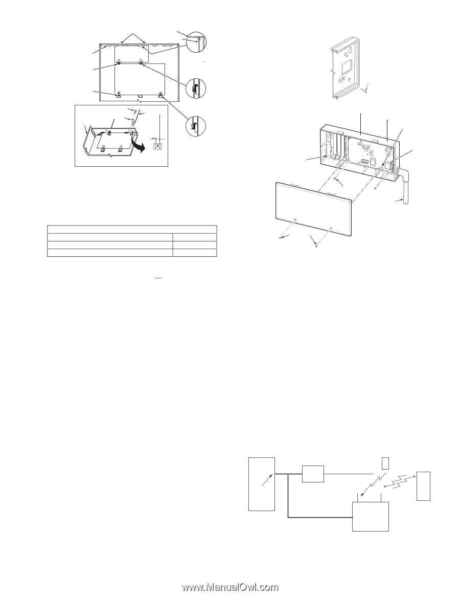
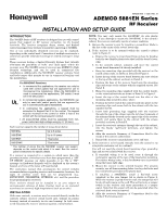
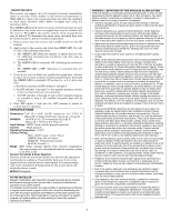
HOLES FOR ANTENNAS AND GROUNDING LUGS CABINET CIRCUIT BOARD BOARD SUPPORTING SLOTS MOUNTING CLIP MOUNTING CLIP CABINET RECEIVER CIRCUIT BOARD (See Detail D) + + CONTROL CIRCUIT BOARD SCREW (2) GROUNDING LUG (2) ANTENNA (2) DETAIL A SIDE VIEW OF BOARD SUPPORTING SLOTS DETAIL B SIDE VIEW OF MOUNTING CLIP SCREW 5881ENHC-001-V0 Figure 2: Tamper Protection FRONT TAMPER (REAR TAMPER) RCVR BRD + + DETAIL D ANTENNA AND GROUNDING LUG INSTALLATION ANTENNA MOUNT (2 PLACES) DETAIL C SIDE VIEW OF MOUNTING CLIP pcb_RF_mount-V0 MOUNTING HOLES 4 (TYP) ECP CONNECTION Figure 1: Installing the Receiver Board in the Control's Cabinet 4. Setting the DIP switches (All Receivers): a. Set the receiver's DIP switch (#2 through #4) to identify the MACHINE SCREWS 4 (TYP) receiver's address (refer to the DIP switch chart in the Summary of Connections Diagram on back cover). PLASTIC CONDUIT b. Verify that DIP switch #1 is in the OFF position. c. Set DIP switch #5 according to the following chart. DIP SWITCH #5 For . . . Set to . . . COVER SECURING SCREWS Commercial Fire Applications ON Non-commercial Fire Applications OFF NOTES: • If multiple receivers are used on one control, DIP switch #5 must be set to the same position on all receivers. • DIP switch #5 reduces sensitivity during supervision message reception. For commercial fire applications, DIP switch #5 must be in the ON position. 5. Insert the wiring plug (with 4 flying leads) into the mating socket on the receiver (see Summary of Connections Diagram on back cover for socket location). Connect the 4 wires to the control's corresponding keypad terminals (see "Interface Wiring" in the SPECIFICATIONS section). 6. Install the antennas in the right-hand terminals of the two terminal blocks at the upper edge of the circuit board, one into each block's right-hand terminal, and tighten the screws to secure them. Caution: Avoid mounting the receiver antennas against a metal surface. 7. Replace the unit's front cover using the supplied screw to secure it. 8. Proceed with any programming of the control that may be necessary for RF operation, and the installation of the system's wireless transmitters, as described in the control's installation and setup guide and the transmitter's installation instructions. NOTES: • The receiver can support up to 16 high security (encrypted) wireless transmitters (keys). The total quantity of wireless keys (encrypted and unencrypted) that can be used is determined by the control panel. • Wireless key buttons must be enrolled to zones in the control panel via zone programming first. If the wireless key is to be 5883HC-001-V0 Figure 3: 5881ENHC UL Commercial Fire Installation (f) repeat (a) through (e) for the receiver that was disconnected. • The RED LED located on the receiver's circuit board should be used as an indicator of strong local radio frequency interference. If this LED is continuously illuminated, the receiver should be relocated. • After a successful enrollment of an encrypted key, the GREEN LED blinks the number of spaces that are free for additional encrypted key enrollment. 9. Replace the receiver's cover. UL Commercial Fire Installation For UL864 Commercial Fire Installations, you will need to purchase separately the "5800BOX" (in which the circuit board will be installed). Follow the instructions below and refer to Figure 3. 1. Mount the rear half of the 5800BOX directly to the wall in the selected location, hinged side up. Secure using the 4 screws provided and insert screw in tamper tab, refer to Installation, step 3c and Fig. 2. 2. Thread the ECP wire through the conduit and feed through the opening at the side of the box rear. 3. Remove the circuit board from the 5881EN case and discard case. Install the circuit board into the 5800BOX and secure using the 4 screws provided. Install each antenna, refer to Installation: Step 6. 4. Connect the ECP terminals as shown. 5. Insert slots on top of box cover into hinges on top of box back and secure using 2 cover securing screws. CONTROL PANEL* 5800 SERIES WIRELESS TRANSMITTERS ECP ISOLATOR TO BURGLARY DEVICES used for arming and disarming the VISTA-40 and up, a user number must then be assigned to the wireless key via user programming. If it is not done in this order, you will be unable to respond successfully to the RF button zone number prompt in user programming. • If more than one receiver is being used and you are using encrypted wireless keys, we recommend that you (a) enter the GO/NO GO mode, (b) disconnect one receiver, (c) enroll all encrypted keys into the connected receiver, (d) reconnect the disconnected receiver, (e) exit the GO/NO GO mode, and then KEYPAD TERMINALS ON CONTROL BOARD TO FIRE DEVICES 2-WAY TRANSMISSION 5881ENHC TRANSCEIVER 2-WAY WIRELESS KEYPAD (e.g. 5804BD) OR 5800RL 2-WAY RELAY MODULE *CONTROL MUST BE CAPABLE OF SUPPORTING A 5800 RF SYSTEM Figure 4: Mounting UL Commercial Fire Applications 5883HC-002-V0 NOTE: For UL-864 Fire installations, ECP Isolator (PN ECP-ISO) is required. 2
-
 1
1 -
 2
2 -
 3
3 -
 4
4
 |
 |