Honeywell 5881ENM Installation Guide - Page 4
ÊN7635-3V4>Š - receiver
 |
UPC - 781410331136
View all Honeywell 5881ENM manuals
Add to My Manuals
Save this manual to your list of manuals |
Page 4 highlights
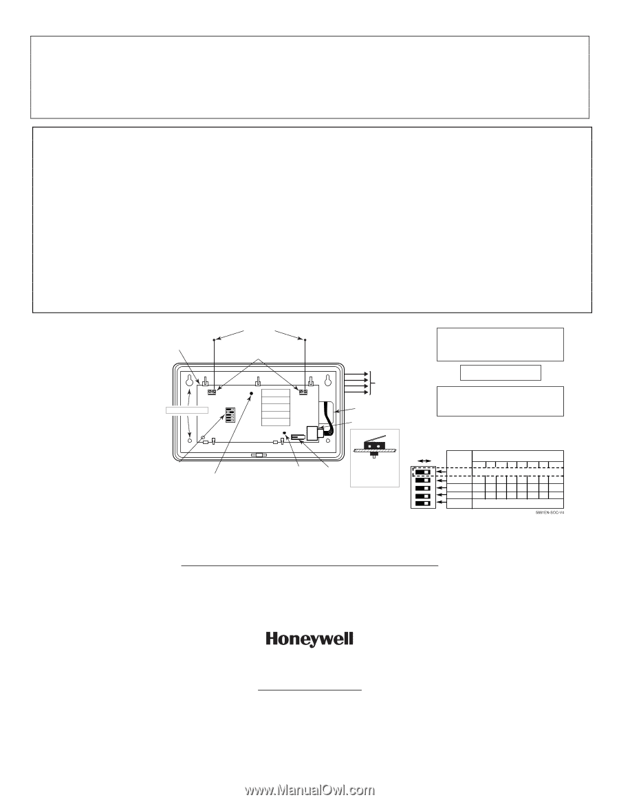
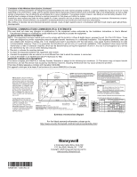
Limitations of this Wireless Alarm System, Continued This system's wireless transmitters are designed to provide long battery life under normal operating conditions. Longevity of batteries may be as much as 7 years, depending on the environment, usage, and the specific wireless device being used. External factors such as humidity, high or low temperatures, as well as large swings in temperature, may all reduce the actual battery life in a given installation. This wireless system, however, can identify a true low battery situation, thus allowing time to arrange a change of battery to maintain protection for that given point within the system. Installing an alarm system may make the owner eligible for a lower insurance rate, but an alarm system is not a substitute for insurance. Homeowners, property owners and renters should continue to act prudently in protecting themselves and continue to insure their lives and property. We continue to develop new and improved protection devices. Users of alarm systems owe it to themselves and their loved ones to learn about these developments. FEDERAL COMMUNICATIONS COMMISSION (FCC) STATEMENTS The user shall not make any changes or modifications to the equipment unless authorized by the Installation Instructions or User's Manual. Unauthorized changes or modifications could void the user's authority to operate the equipment. CLASS B DIGITAL DEVICE STATEMENT NOTE: This equipment has been tested and found to comply with the limits for a Class B digital device, pursuant to part 15 of the FCC Rules. These limits are designed to provide reasonable protection against harmful interference in a residential installation. This equipment generates, uses and can radiate radio frequency energy and, if not installed and used in accordance with the instructions, may cause harmful interference to radio communications. However, there is no guarantee that interference will not occur in a particular installation. If this equipment does cause harmful interference to radio or television reception, which can be determined by turning the equipment off and on, the user is encouraged to try to correct the interference by one or more of the following measures: • Reorient or relocate the receiving antenna. • Increase the separation between the equipment and receiver. • Connect the equipment into an outlet on a circuit different from that to which the receiver is connected. • Consult the dealer or an experienced radio/TV technician for help. INDUSTRY CANADA (IC) STATEMENTS This device complies with RSS210 of Industry Canada. Operation is subject to the following two conditions: (1) This device may not cause harmful interference, and (2) This device must accept any interference received, including interference that may cause undesired operation. This Class B digital apparatus complies with Canadian ICES-003. Cet appareil numérique de la classe B est conforme à la norme NMB-003 du Canada. NOTE: WHEN CIRCUIT BOARD IS MOUNTED IN CONTROL'S CABINET, GROUNDING LUGS (2) PROVIDED MUST BE INSERTED IN LEFT-HAND TERMINALS OF ANTENNA BLOCKS AND SECURED TO CABINET (SEE RECEIVER'S AND CONTROL'S INSTRUCTIONS). WHEN BOARD IS MOUNTED IN A SEPARATE CABINET (COMMERCIAL FIRE APPLICATION), DO NOT USE THE GROUNDING LUGS. CIRCUIT BOARD MOUNTING HOLES ANTENNAS INSERT IN RIGHT-HAND TERMINALS 5881EN SERIES 5881ENL 5881ENM 5881ENH 5881ENHC USE MAX. OF 220 ft. (67m) OF #22 (0.64mm) WIRE OR 550 ft. (168m) OF #18 (1mm) WIRE FOR EACH RUN. 20 ft. MAX. IN COMMERCIAL FIRE INSTALLATIONS. (SEE RECEIVER'S INSTRUCTIONS). THIS DEVICE COMPLIES WITH PART 15 OF FCC RULES AND RSS210 OF INDUSTRY CANADA. OPERATION IS SUBJECT TO THE FOLLOWING TWO CONDITIONS: (1) THIS DEVICE MAY NOT CAUSE HARMFUL INTERFERENCE, AND (2) THIS DEVICE MUST ACCEPT ANY INTERFERENCE RECEIVED, INCLUDING INTERFERENCE THAT MAY CAUSE UNDESIRED OPERATION. YELLOW RED BLACK GREEN TO CONTROL'S KEYPAD TERMINALS. EACH RECEIVER MUST BE ON INDIVIDUAL HOME RUN. DIP SWITCH #5 FCC ID CFS8DL5882A CANADA:17481021751A ON: FOR USE IN COMMERCIAL FIRE APPLICATIONS. WIRING OPENING (SEE THE RECEIVER'S INSTRUCTIONS). OFF: USE IN NON-COMMERCIAL FIRE INSTALLATIONS. PLUG & SOCKET DIP SWITCH: WHITE AREAS = SWITCH HANDLES POSITION 2-4: DETERMINE RECEIVER'S ADDRESS FRONT OF PC BOARD CONSULT CONTROL'S INSTRUCTIONS FOR ADDRESS TO USE. TO RELEASE CIRCUIT BOARD, BEND BACK BOTTOM TABS (2). FOR COMMERCIAL FIRE APPLICATION. USE TWO SCREWS (NOT SUPPLIED) WITH INSULATING WASHERS BENEATH THE HEADS. TO MOUNT BOARD IN SEPARATE CABINET. (SEE RECEIVER'S INSTRUCTIONS). DIP SWITCH INTERFERENCE SEE GREEN LED: NORMALLY OFF INDICATOR LED DETAIL A ONE SHORT FLASH - RF MESSAGE DECODED ONE LONGER FLASH - COMMAND RECEIVED FROM CONTROL FOUR FLASHES - ENCRYPTED TRANSMITTER SUCCESSFULLY ENROLLED BACK OF PC BOARD DETAIL A FRONT AND REAR TAMPER 5881ENHC ONLY Summary of Connections Diagram DIP SWITCH BELOW SHOWN SET FOR ADDRESS "0". SWITCH RECEIVER ADDRESS SETTINGS ON OFF POSITION ("-" means "OFF") 0123456 7 5 5 (SEE TEXT ABOVE) 4 4 - ON - ON - ON - O N 3 3 - - ON ON - - ON ON 2 2 - - - - ON ON ON ON 1 1 MUST BE IN OFF POSITION 5881EN-SOC-V4 For the latest warranty information, please go to: http://www.security.honeywell.com/hsc/resources/wa/index.html ÊN7635-3V4>Š N7635-3V4 11/08 Rev. B 2 Corporate Center Drive, Suite 100 P.O. Box 9040, Melville, NY 11747 Copyright 2009 Honeywell International Inc. www.security.honeywell.com
-
 1
1 -
 2
2 -
 3
3 -
 4
4
 |
 |