Honeywell 5897-35 Installation Instructions
Honeywell 5897-35 Manual
 |
View all Honeywell 5897-35 manuals
Add to My Manuals
Save this manual to your list of manuals |
Honeywell 5897-35 manual content summary:
- Honeywell 5897-35 | Installation Instructions - Page 1
5897-35 RF DUAL TEC Motion Sensor Installation Instructions GENERAL INFORMATION The 5897-35 motion sensor combines dual technology motion detection with reliable 5800 wireless RF in one small package. Within the protected area, the passive infrared (PIR) detector senses changes in infrared energy - Honeywell 5897-35 | Installation Instructions - Page 2
5897-35 RF DUAL TEC Motion Sensor Installation Instructions MICROWAVE SUPERVISION If the microwave technology stops sending or receiving signals, the sensor will lock into an alarm. The LEDs at the sensor, however, will not light. If the microwave regains its signal, the sensor will return to - Honeywell 5897-35 | Installation Instructions - Page 3
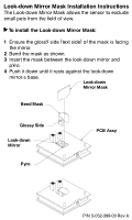
t Look-down Mirror Mask Installation Instructions The Look-down Mirror Mask allows the sensor to exclude small pets from the field of view. To install the Look-down Mirror Mask: 1 Ensure the glossy side (text side) of the mask
-
 1
1 -
 2
2 -
 3
3
 |
 |
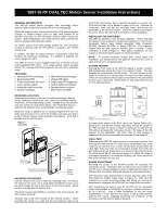
5897-35 RF DUAL TEC Motion Sensor Installation Instructions
GENERAL INFORMATION
The 5897-35 motion sensor combines dual technology motion
detection with reliable 5800 wireless RF in one small package.
Within the protected area, the passive infrared (PIR) detector senses
changes in infrared energy (such as body heat emitted by an
intruder), and turns on the microwave detector which senses the
motion.
Both technologies must verify intrusion within a preset time
interval, virtually eliminating false alarms.
To reduce current drain and prolong battery life, the microwave
circuitry is dormant until the PIR detects a change in the infrared
energy level.
In addition, the 5897-35 sensor features a supervision circuit that
monitors the microwave technology.
If a problem is detected, the
sensor will go into alarm.
The 5897-35 sensor is also equipped with both a Fresnel lens and
multi-segmented PIR mirror.
This unique optical system provides
dense PIR coverage from directly beneath the unit out to maximum
range.
FEATURES
•
Microwave/PIR technology
•
5800 Wireless technology
•
Dual element PIR
•
Unique PIR optics
•
Three minute hold off circuit
•
Single edge PIR triggering
•
Cover tamper switch
•
Lithium batteries included
•
Automatic walk-test mode
•
Simple installation
•
Optional barrier and pet-
alley lenses available
MOUNTING LOCATION
Select the best location in the room for both technologies.
Aim the
sensor toward the interior of the room, away from windows, moving
machinery, and heating/cooling sources.
Do
NOT
mount the detector
near wire screens or large metal objects.
We recommend that you
verify the RF reception prior to permanently mounting the sensor.
Maximum range is obtained at a mounting height of 7'6" (2.3 m).
Make sure the sensor has a clear line of sight to all areas you wish to
protect. Infrared energy cannot penetrate solid objects.
If the PIR is
blocked, the unit will not alarm.
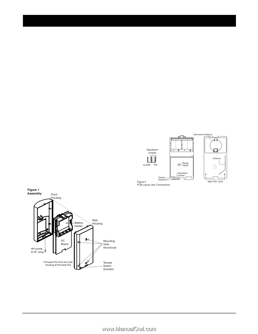
MOUNTING PROCEDURE
Use the sensor's rear cover to mark the mounting holes.
To remove
the sensor's rear cover, use a small-blade screwdriver to push up on
the latch through the slot in the bottom of the front housing.
Gently
pull the housings apart at the base first.
The printed circuit board (PCB) is mounted in the front housing.
Do
NOT remove the PCB.
Securely mount the rear housing at the desired location.
When
mounting the sensor on a wall, use the two knockout holes in the
back of the rear housing.
When mounting the sensor in a corner, use
the knockout holes on the beveled corners of the unit.
Remove the
knock-outs, mark and drill the mounting holes, and mount the
transmitter at the desired location.
Install the batteries and replace
the cover; secure the cover with a #4 (5/16-in.) screw (supplied).
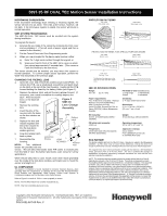
INSTALLING THE BATTERIES
The 5897-35 operates on four 3V lithium batteries.
Please note that
the batteries must always be installed and replaced in a set of four!
Acceptable battery types include Honeywell #466, Panasonic
CR123A, Duracell DL-123A, or Sanyo CR123A.
Four batteries,
shipped with the unit, must be installed prior to testing.
Proper
orientation is shown in Figure 2.
After battery installation, the unit
requires a 60-second warm-up prior to normal operation.
NOTE:
To prevent excessive battery drain during setup and
installation, you should remove the batteries whenever the cover is
open and the unit is not being tested.
SYSTEM TESTING
Opening the front cover of the 5897-35 signals a tamper condition
and automatically places the unit in the walk-test mode.
This also
disables the three-minute hold off circuit.
The unit remains in this
mode for a period of 8 minutes after the cover has been replaced.
There are two walk-test LEDs located at the bottom of the unit behind
the lens, one on each side.
These LEDs are only active while the unit
is in the walk-test mode.
A jumper at the bottom of the PCB, next to the Tamper Switch (S1),
allows you to test the PIR section separately. Placing the jumper in
the "PIR" position, as shown in Figure 2, allows you to walk-test the
PIR without activating the microwave circuits. The range of the PIR
detector is not adjustable. The PIR's field of view (range) is
determined by the mounting height and the type of lens installed.
WALK-TEST
Walk-testing the 5897-35 motion sensor is a two-stage process. The
first step is to walk-test the PIR. Walk across the protected area at the
ranges to be covered. Two to four normal steps should make the
LEDs light. Since the LEDs are connected in parallel, both LEDs will
light at the same time. When there is no motion in the protected area,
the LEDs should be off. The second stage is to adjust the range of
microwave transmitter. For continued reliability, the sensor should be
walk-tested at least once per year.
RANGE ADJUSTMENT
Returning the jumper to the ALARM position will reactivate the
microwave circuits.
Remember that as long as the cover is open, the
hold off circuit remains disabled. In order to adjust the microwave, the
PIR must first see motion, which will activate the microwave circuitry.
The microwave range potentiometer is located near the center of the
PCB below the battery holder (refer to Figure 2).
With the PCB
oriented in its correct mounting position and facing you, turning the
potentiometer clockwise will INCREASE the range of the microwave.
After determining the field of view for the PIR, set the microwave
range potentiometer at MINIMUM by turning it counterclockwise as
far as it will go.
(Use a small screwdriver to turn the range
potentiometer.)
Then, with the test jumper in the ALARM position,
walk-test the sensor, gradually increasing the sensitivity of the
microwave until the desired range is obtained.