Honeywell 6128 Installation Instructions
Honeywell 6128 Manual
 |
View all Honeywell 6128 manuals
Add to My Manuals
Save this manual to your list of manuals |
Honeywell 6128 manual content summary:
- Honeywell 6128 | Installation Instructions - Page 1
only. Previous Menu N6484V3 3/96 5827BD and 5827BDE WIRELESS BI-DIRECTIONAL KEYPADS Used with 5800TM Transmitter Module INSTALLATION INSTRUCTIONS and OPERATING GUIDE Unless otherwise indicated, all information in this manual is applicable to both the 5827BD and 5827BDE GENERAL INFORMATION The - Honeywell 6128 | Installation Instructions - Page 2
keypad is used. This depends on the type of control used and its programming. Refer to the control's installation manual Transmitter Module Installation Installation instructions accompany the 5800TM, location for the 5800TM as for the system's RF receiver, to ensure good transmission and reception. - Honeywell 6128 | Installation Instructions - Page 3
RF TRANSMISSION IN PROGRESS OR RECEPTION JUST COMPLETED and, as explained in the INSTALLATION section for the wireless keypad: RED & GREEN ALTERNATELY BLINKING SILENT 5827BD/5827BDE IS IN KEYPAD of other wired keypads used with the system (as described in the system's User's Manual). Press the - Honeywell 6128 | Installation Instructions - Page 4
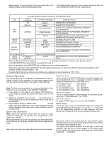
indicated on the previous pages for both a 5827BD and 5827BDE. * 5881EH RF receivers must be set to the high security mode (DIP switch #1 ON) the control panelÕs instructions for the entry required. 2. Power up the 5827BDE keypad (press [5 ] key), and place the unit in the keypad programming mode by - Honeywell 6128 | Installation Instructions - Page 5
by keying [ 5] + [#]. If all 5827BDEs in the system have been successfully returned to their normal mode, the yellow SEND/RCV LED (only) on the wireless keypad will blink once. If not, the 5827BDEs were not returned to their normal mode, and you will need to repeat steps 2 through 4. Note that when - Honeywell 6128 | Installation Instructions - Page 6
in materials and workmanship under normal use and service for 18 months from the date stamp control on the product or, for products not having an Ademco date stamp, for 12 months from date of original purchase unless the installation instructions or catalog sets forth a shorter period, in which
-
 1
1 -
 2
2 -
 3
3 -
 4
4 -
 5
5 -
 6
6
 |
 |

N6484V3˚ 3/96
5827BD and 5827BDE
WIRELESS BI-DIRECTIONAL KEYPADS
Used with 5800TM Transmitter Module
INSTALLATION INSTRUCTIONS and OPERATING GUIDE
Unless otherwise indicated, all information in this manual is applicable to both the 5827BD and 5827BDE
GENERAL INFORMATION
T
he 5827BD and 5827BDE Wireless Bi-directional Keypads are
designed to be used in conjunction with a 5800TM Transmitter
Module. Additional 5827BDs (any quantity) may be used in
conjunction with the same 5800TM; however, no more than eight
5827BDEs may be used. The 5800TM is compatible with any
control panel that is
also
equipped with a 4281 type (5700 System)
or 5881 type (5800 System) RF receiver.
Note:
The 5827BDE is an enhanced version of the 5827BD and
employs Ademco°s new SignalSentry“ technology, which
can provide high security wireless transmissions when used
in conjunction with the 5881EH RF receiver.
The 5827BD and 5827BDE can operate the protection system
similarly to other wireless keypads, via keypad buttons.
In addition,
three LEDs (Red, Green, and Yellow) and a piezoelectric sounder
can indicate status information relative to:
System arming/trouble/emergency, RF transmission/confirmation,
and 5827BD/5827BDE programming and power.
The keypad configuration is similar to that of standard keypads. The
[
] key, however, is also the [ON/STAT] (power-up and system
status inquiry) key instead of a "READY" key, as it is on other
keypads (see
OPERATION
).
There are three panic keys: A, B, and
C, comparable to the individual keys (or panic key pairs of [1] & [
]
,
[
]
& [#], and [3] & [#] respectively) on other keypads.
The 5827BD and 5827BDE keypads, if so-programmed, also
feature "Quick Key" operation, which allows use of the [#] key
instead of entry of the security code when performing functions.
5800TM Transmitter Module
For every installation of one or more 5827BD or 5827BDE Wireless
Keypads, one 5800TM is required. The 5800TM complements the
RF receiver in that it transmits the information to be displayed on, or
sounded by, the 5827BD or 5827BDE.
No modification to the
control is necessary. The 5800TM connects directly to the control’s
wired keypad connection points, as described later.
ARM
OFF
AWAY
STAY
MAXIMUM
TEST
BYPASS
INSTANT
ON/STAT
CODE
CHIME
SEND/RCV
READY
1
2
3
4
5
6
7
8
9
*
0
#
ANTENNA
(OPTIONAL)
SOUNDER
PANIC KEYS
POWER-UP KEY
AFFIX
PANIC KEY
LABELS HERE
LEDS
GREEN
YELLOW
RED
C (3/#)
B (
/#)
A (1/
)
5827BD & 5827BDE INSTALLATION
The 5827BD and 5827BDE are designed to be portable, for use
throughout the protected premises.
If desired, a wireless keypad
may be stored on its accompanying mounting bracket (easily
installable via two countersunk mounting holes). Keyhole slots on
the rear of the keypad slip onto two hooks on the mounting bracket,
allowing the keypad to be easily removed when desired .
When operating, or selecting a location for storing the wireless
keypad, observe the same precautions as used for locating the
wireless system’s other transmitters (see the control panel’s
instruction manual). For example, operating the keypad on or near
large metal objects may decrease range and/or block
transmissions.
1.
Install the keypad’s 9-volt Alkaline battery.
S
lide off the
battery compartment cover at the rear of the keypad and insert
the battery. Observe polarity!
Then replace the cover.
2.
Program the keypad’s memory
as indicated next.
Programming the Wireless Keypad
a.
Power up the keypad
by depressing the [
] key.
The
yellow LED will blink.
If the keypad was previously programmed, the system
status may also be annunciated (see
Power-up and
System Status Inquiry
on the next page).
b.
Enter the keypad programming mode
by
depressing both the [1] and [3] keys at the same time
for 3 seconds.
Alternate blinking of the red and green LEDs confirms
that the unit is in the keypad programming mode.
c.
Program the desired functions, in the order given
in the Programming table that follows.
Note that
every sequence starts with a [
] and ends with a [#].