Honeywell CT1503 Owner's Manual
Honeywell CT1503 Manual
 |
View all Honeywell CT1503 manuals
Add to My Manuals
Save this manual to your list of manuals |
Honeywell CT1503 manual content summary:
- Honeywell CT1503 | Owner's Manual - Page 1
CTl500, CT1501, CT1502, CT1503 ELECTROMECHANICAL FUEL SAVER THERMOSTAT AND WALLPLATEEUBBASE CTI500-24 V gas ON LINE VOLTAGE (120 V) SYSTEMS. INSTALLATION MANUAL Any questionsconcerningthe applicationofthis thermostat should be directedto HoneywellConsumer Services at 1-800-468-1502, Monday-Friday 7 - Honeywell CT1503 | Owner's Manual - Page 2
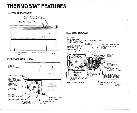
FEATURES I-Front of thermostat. HlGH TEMPERATURE 1 CONTROL LEVER (RED) LOW TEMPERATURE CONTROL LEVER (BLUE)- Ill-Cover removed. 24 HOUR PROGRAM DIAL 'THERMOSTAT COVER THERMOMETER 1 11.711 Il-Hinged cover lifted. .. .~ . ,..... . PROGRAM PINS A "--- CAPTIVE MOUNTING ANTICIPATOR HIND - Honeywell CT1503 | Owner's Manual - Page 3
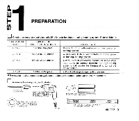
circuit For gas or oil heating/cooling system. CT1502 CT1503 Q682B1227 Subbase 199986D Wailp ate 4-wire, 15 to 30 volt control circuit. For single stage heat pump or central electric heatinglcooling systems that require the thermostat to control the fan in heatino. [ 750 mill volt single-stage - Honeywell CT1503 | Owner's Manual - Page 4
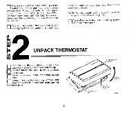
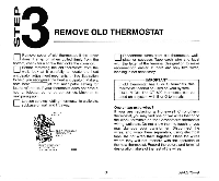
and Adapter Ring (see appropriate figure under step 4). Call Honeywell Consumer Services (1-800-468-1502) for ordering information, Monday-Friday, 7:30 i2 F UNPACK THERMOSTAT 0 0Remove and discard shipping wrap. Save package of screws, instructions and receipt Remove thermostat cover by lifting - Honeywell CT1503 | Owner's Manual - Page 5
on a system with B or 0 terminals. One or two extra wires? If you are replacing a Honeywell Chronotherm thermostat,you may find one or two wires that go to the clock terminals on the Chronotherm thermostat wiring wallplate. Do not allow them to touch, or you may damage your transformer. Disconnect - Honeywell CT1503 | Owner's Manual - Page 6
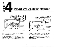
"4 b MOUNT WALLPLATE OR SUBBASE 10 If mounting on outlet box, mount as shown on appropriate figure. bIfamseoui.nnti'pnogsoi.tn.ionwaalln, dhomldarwkahlloplleasteoonr subwall. Use spirit level to make sure wallplate or sub- base will be level. Drill 3/16 in. holes and gently tap anchors into - Honeywell CT1503 | Owner's Manual - Page 7
nCarefully level the wallplate or subbase and firmly u tighten screws. .. SPIRIT LEVEL ''wm WALLPLATE SCREWS "2) 5 69-0273-9 - Honeywell CT1503 | Owner's Manual - Page 8
WALLPLATE OR SUBBASE 0 .: -MOTE:All wiring must comply with local electrical codes and ordinances. Refer to illustration and strip thermostat wire insulation as necessary. - F. "-r.n.~S.T.F..ldilR.U.T CONNECTION- For CT1500 heating-only 0 , FOR WRAPAROUND CONNECTIONSTRlP7116In. [11 mml BARRIER - Honeywell CT1503 | Owner's Manual - Page 9
" If the labels do not agree with the terminal designations on your new subbase Refer to Table 2 on page 8 Determine correct hookup from the listed control function and the equipment control circuit 7 69-0273-9 ~ ~ - Honeywell CT1503 | Owner's Manual - Page 10
valve or damper control circuit. 0 Cooling changeover valve or damper control circuit. P Heat pump compressor control Push excess wire back into wall. and plug hole in wall with nonflammable insulation to prevent drafts from affecting thermostat operation. For CT1502 heatinglcooling - Honeywell CT1503 | Owner's Manual - Page 11
WIRETO"Y"AND0NE TO " W . U S t ' Y AND " W ' O N NEW THERMOSTAT, DO NOT U S E " P . IMPORTaNT- IF OLD THERMOSTAT USES A W2 (AUXILIARY OR EMERGENCY HEAT) TERMINAL, THIS THERMOSTAT MAY NOT BE USED THIS THERMOSTAT IS NOT DESIGNED TO CONTROL AUXILIARY HEAT A SOMEHEATPUMPSUSE"B"INSTEAD0F"O' M211511 - Honeywell CT1503 | Owner's Manual - Page 12
- L MOUNT THE THERMOSTAT or subbase as shown in illustration. Do NOT cycle heating system until Step 7 is completed. 10 - Honeywell CT1503 | Owner's Manual - Page 13
SET HEAT ANTICIPATOR LEVER - NOTE: Not applicable on CT1503 millivolt model. 0The thermostat's adjustable heat anticipator must be correctly set to accurately control the on-time length of the system. An incorrect setting can result in room temperature swings or burn out the anticipator and void - Honeywell CT1503 | Owner's Manual - Page 14
indicator to match the number you recorded in Step 4 or found on the primary control as shown above, or as recorded in Step 7 "8INSTALL F TIMER BATTERIES 0 \ANTICIPATOR SETTING LEVER 11,7164\ teries in thermostat as shown. Once a year, or when batteries are dead, replace with two new AAA - Honeywell CT1503 | Owner's Manual - Page 15
SET TIMER 0Adjust the timer by moving the knob in clockwise direction. Do NOT reverse the knob. When time is correctly set, the Time Indicator Arrow (see illustration) must point to the correct time and the corresponding daytime (lighr) or nighitime (dark) portion of the program dial. 13 - Honeywell CT1503 | Owner's Manual - Page 16
"10 0I- ATTACH THERMOSTAT COVER 0Make sure the packing inserts in the thermostat base have been removed. as explained in step 3 0Place the two tabs on upper edge of cover into mounting slots in thermostat base 0Swing cover downward until it engages catch at bottom of base .. 14 - Honeywell CT1503 | Owner's Manual - Page 17
the low and high temperature for energy savings and comfort control, as shown in illustration. LOW TEMP.lBL"E MARK1 SET LEVER 1 Do NOT check operation by shorting across terminals of relay or valve coil; this will burn out the thermostat heat anticipator, which will void the warranty. I 15 69 - Honeywell CT1503 | Owner's Manual - Page 18
least one complete cycle. IMPORTANT If thermostat fails any test, refer to troubleshooting guide in owner's manual. Heating/Cooling System 0 Turn on any time delay that may be built into the compressor control circuit. 0 Movebothleverstogether5°F[30C]aboveroom temperature. The cooling equipment - Honeywell CT1503 | Owner's Manual - Page 19
you wantfor normal comfort periods. REFER TO THE OWNERS MANUAL FORM 690333FOR OPERATING AND PROGRAMMING INSTRUCTIONS. IF YOU HAVE OUESTIONS REGARDING THE INSTALLATION OF THE HONEYWELL FUEL SAVER THERMOSTAT, PLEASECALL OUR TOLLFREE CONSUMER SERVICES GROUP NUMBER AT 1-800-468-1502, MONDAY-FRIDAY, 7:30 - Honeywell CT1503 | Owner's Manual - Page 20
Residential and Building Controls Division Honeywell Inc. 1985 Douglas Drive No. Golden Valley, MN 55422 Residential and Building Controls Division Honeywell Limited-Honeywell 740 Ellesmere Road Scarborough, Ontario M1P 2VY Lunltke Honeywell Helping You Conlrol Your World
-
 1
1 -
 2
2 -
 3
3 -
 4
4 -
 5
5 -
 6
6 -
 7
7 -
8
-
9
-
10
-
11
-
12
-
13
-
14
-
15
-
16
-
17
-
18
-
19
-
20
 |
 |

CTl500, CT1501,
CT1502,
CT1503
ELECTROMECHANICAL FUEL SAVER
THERMOSTAT AND
WALLPLATEEUBBASE
CTI500-24
V
gas
or
oil heat.
CTl501-24
V
gas
or
oil
heat/cool.
CTI502--24
V
central electric heat/cool
or
single stage heat
pump
without
auxiliary heat.
CTI
503-750
millivolt heat.
NOT
FOR USE
ON LINE VOLTAGE (120
V)
SYSTEMS.
INSTALLATION MANUAL
Any questions concerning the application
of
this thermostat should be directed to HoneywellConsumer Services
at
1-800-468-1502,
Monday-Friday
730
a.m.-500 pm., Central time.
S.M.
Rev.
7-91
aHoneywell
Inc.
1991
Form
Number
69-0273-9