Honeywell CT70A Owner's Manual
Honeywell CT70A Manual
 |
View all Honeywell CT70A manuals
Add to My Manuals
Save this manual to your list of manuals |
Honeywell CT70A manual content summary:
- Honeywell CT70A | Owner's Manual - Page 1
suitability for your home's system by reviewing the ratings listed on the front of these instructions and reviewing the CT70 Heat Pump Thermostat Wiring Guide enclosed. Make certain that your home's heat pump system is working, especially if it has been inoperative for a length of time. If the - Honeywell CT70A | Owner's Manual - Page 2
on the back of the thermostat according to the labels you placed on the wires or as shown in the wiring diagram. SYSTEM MONITOR CHANGEOVER RELAY (COOL) L1 (HOT) L2 1 FAN RELAY EM. HEAT RELAY AUX. HEAT RELAY BACK OF DEVICE CHANGEOVER RELAY (HEAT) HEAT RELAY 1 1 POWER SUPPLY. PROVIDE - Honeywell CT70A | Owner's Manual - Page 3
of the device. Install two screws in top mounting holes and tighten. Replace the thermostat cover. 5 CHECK OUT THERMOSTAT Turn on the power to the heat pump system. To check heating, move the system switch on the thermostat to HEAT and the fan switch to AUTO. Move the set point lever to about 10o - Honeywell CT70A | Owner's Manual - Page 4
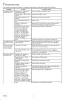
Honeywell thermostat requires little or no attention. Most problems can generally be traced to the following: Symptom Compressor doesn't provide warm air. Problem Equipment has compressor protection time delay. System switch at OFF or COOL position. Blown fuse or tripped circuit breaker. Heat pump - Honeywell CT70A | Owner's Manual - Page 5
any time during the warranty period, the product is defective or malfunctions, Honeywell shall repair or replace it (at Honeywell's option) within a reasonable period of time. If the product is defective, (i) return it, with a bill of sale or other dated proof of purchase, to the hardware or home - Honeywell CT70A | Owner's Manual - Page 6
-
 1
1 -
 2
2 -
 3
3 -
 4
4 -
 5
5 -
 6
6
 |
 |

CT70A
Heat Pump Thermostat
Your Honeywell Thermostat
Your new Honeywell CT70A Heat Pump Thermostat
provides low voltage (24 Vac) control of two-stage heating
and one-stage cooling in heat pump systems, using
manual changeover. Light-emitting diodes (LEDs) provide
emergency heat and auxiliary heat indication.
Recycling Notice
This control contains mercury in a sealed tube. Do not
place control in the trash at the end of its useful life.
Installation Instructions
Thermometer Scale Range: 45
o
F to 85
o
F [7
o
C to 29
o
C].
Electrical Ratings: 24 to 27 Vac.
Do-It-Yourself Models
If this control is replacing a control that contains mercury in
a sealed tube, do not place your old control in the trash.
Contact your local waste management authority for
instructions regarding recycling and the proper disposal of
this control, or of an old control containing mercury in a
sealed tube.
If you have questions, call Honeywell Inc. at
1-800-468-1502.
1
PREPARATION
Your Honeywell thermostat should be properly
installed if you follow these instructions step-by-step.
It is recommended that as you read, understand and
complete each step, you check
✔
it off with pencil or pen.
Check thermostat suitability for your home’s system
by reviewing the ratings listed on the front of these
instructions and reviewing the CT70 Heat Pump Thermo-
stat Wiring Guide enclosed.
Make certain that your home’s heat pump system is
working, especially if it has been inoperative for a
length of time. If the system does not work, contact your
local heating dealer for assistance.
Carefully unpack your new thermostat. Save
packages of screws, instructions, receipt and proof-
of-purchase.
2
THERMOSTAT MOUNTING DIMENSIONS
S.M.
•
8-94
•
Printed in U.S.A.
•
•
©Honeywell Inc. 1994
•
Form Number 69-0846
80
70
60
50
80
70
60
50
3
[83]
9
32
AUTO
ON
EM. HEAT
HEAT
OFF
COOL
EM. HEAT
AUX. HEAT
3
[101]
31
32
4
[119]
11
16
3
[83]
9
32
2
[52]
1
16
3
16
[5]
9
32
1
[33]
3
8
[10]
1
2
[13]
11
32
[9]
3
8
[10]
M7306