Honeywell H8908ASPST Installation Instructions
Honeywell H8908ASPST - Manual Humidistat Control Manual
 |
UPC - 085267312493
View all Honeywell H8908ASPST manuals
Add to My Manuals
Save this manual to your list of manuals |
Honeywell H8908ASPST manual content summary:
- Honeywell H8908ASPST | Installation Instructions - Page 1
the thermostat. INSTALLATION INSTRUCTIONS Fig. 1. H8908A,D control. Humidity Control Régulateur d'humidité OUTDOOR TEMPERATURE -20 °F -10 °F 0 °F +10 °F +20 °F Over 20 °F -30 °C -25 °C -20 °C -10 °C -5 °C Over 0 °C HUMIDITY SETTING 15% 20% 25% 30% 35% 40% M24726 HOLE FOR WIRING THE DUCT - Honeywell H8908ASPST | Installation Instructions - Page 2
H8908A/B HUMIDISTAT H8908C/D DEHUMIDISTAT DUCT INSTALLATION 1. Choose a location on the duct. RETURN AIR ALTERNATE LOCATION RETURN AIR REMOTE MOUNT INSTALLATION 1. Choose a location in the living area. NOTE: Select a location clear of drafts or excessive humidity. Avoid mounting near doors or - Honeywell H8908ASPST | Installation Instructions - Page 3
mount, slide the black gasket onto the base bracket. See Fig. 8. NOTE: Use gasket only when mounting the control to ductwork. Leave off when mounting to a wall. H8908A/B HUMIDISTAT H8908C/D DEHUMIDISTAT M24733 Fig. 8. Seal base bracket. 5. Secure the base bracket to the duct or remote loca- tion - Honeywell H8908ASPST | Installation Instructions - Page 4
models, only the two yellow wires are connected to the control. The remaining two red wires are only used with electronic humidity controls. 6. Using wire nuts, connect the low-voltage wire to the leads on the H8908 humidistat. See Fig. 6-19 for different wiring configurations. H8908 L1 (HOT) L2 - Honeywell H8908ASPST | Installation Instructions - Page 5
WIRING TERMINALS 1 HUMIDISTAT TERMINALS 1 24V WIRING. HUMIDIFIER 1 TO SYSTEM FAN NOTE: FOLLOW THE INSTALLATION INSTRUCTIONS INCLUDED WITH THE STEAM HUMIDIFIER TO WIRE THE SYSTEM FAN. M24731 Fig. 16. Wiring air frais M24732 Fig. 19. Typical wiring diagram for HR150, HR200, ER150 and ER200 - Honeywell H8908ASPST | Installation Instructions - Page 6
H8908A/B HUMIDISTAT H8908C/D DEHUMIDISTAT CHECKOUT Turn the H8908 dial to "ON" to test proper installation. See Fig. 20. You will hear an audible click if installed correctly, and water will begin flowing to the humidifier. Humidity Control Régulateur d'humidité OUTDOOR TEMPERATURE -20 F -10 F 0 - Honeywell H8908ASPST | Installation Instructions - Page 7
H8908A/B HUMIDISTAT H8908C/D DEHUMIDISTAT 7 69-1341EF-01 - Honeywell H8908ASPST | Installation Instructions - Page 8
H8908A/B HUMIDISTAT H8908C/D DEHUMIDISTAT Automation and Control Solutions Honeywell International Inc. Honeywell Limited-Honeywell Limitée 1985 Douglas Drive North 35 Dynamic Drive Golden Valley, MN 55422 Toronto, Ontario M1V 4Z9 customer.honeywell.com ® U.S. Registered Trademark © 2007 - Honeywell H8908ASPST | Installation Instructions - Page 9
Humidistat H8908A/B Déshumidistat H8908C/D APPLICATION Les humidistats APPAREIL... 1. Lire attentivement les présentes instructions. Le fait de ne pas les suivre NOTICE TECHNIQUE Fig. 1. Régulateur H8908 A et D. M24726 Humidity Control Régulateur d'humidité OUTDOOR TEMPERATURE -20 F -10 F - - Honeywell H8908ASPST | Installation Instructions - Page 10
HUMIDISTAT H8908A/B DÉSHUMIDISTAT H8908C/D INSTALLATION SUR UNE GAINE 1. Choisir l'emplacement calibre 18 à 22. Prévoir une quinzaine de centimètres (6 po) de fil pour effectuer le raccordement de l'humidistat. Fig. 6. Choisir l'emplacement dans la pièce. 2. Découper un trou de 2,5 cm (1 po) pour - Honeywell H8908ASPST | Installation Instructions - Page 11
: Utiliser la garniture seulement pour une installation sur une gaine. Ne pas l'utiliser dans le cas d'une installation sur un mur. HUMIDISTAT H8908A/B DÉSHUMIDISTAT H8908C/D M24733 Fig. 8. Poser la garniture d'étanchéité. 5. Poser la plaque de montage sur la gaine ou à l'emplacement choisi dans - Honeywell H8908ASPST | Installation Instructions - Page 12
SOUS TENSION) ALIMENTATION L2 1 COMMANDE DU VENTILATEUR FAN CONTROL 30 20 40 50 10 60 OFF ON 2 RELAIS COMMUTATION TRANSFORMATEUR BIPOL. UNIDIR. HL C MOTEUR VENTILATEUR 2 VITESSES M24734 Fig. 10. Raccorder l'humidistat. 7. Pour monter l'humidistat, accrocher les deux charnières au haut du - Honeywell H8908ASPST | Installation Instructions - Page 13
HUMIDISTAT H8908A/B DÉSHUMIDISTAT H8908C/D H8908 30 40 20 50 10 60 2 OFF ON FILS 10 60 OFF ON 1 1 BORNES DE L'HUMIDISTAT 1 CÂBLAGE 24 V c.a. HUMIDIFICATEUR VERS LE VENTILATEUR DU SYSTÈME REMARQUE : SUIVRE LES INSTRUCTIONS D'INSTALLATION DE L'HUMIDIFICATEUR À VAPEUR POUR RACCORDER - Honeywell H8908ASPST | Installation Instructions - Page 14
HUMIDISTAT H8908A/B DÉSHUMIDISTAT H8908C/D THERMOSTAT VISIONPRO® Y2 RC L R A W W2 Y S1 G S2 C H8908D RELAIS DE CHAUFFAGE OU BOBINE DE LA VANNE BOBINE DU BOBINE DU CONTACTEUR DE RELAIS - Honeywell H8908ASPST | Installation Instructions - Page 15
HUMIDISTAT H8908A/B DÉSHUMIDISTAT H8908C/D VÉRIFICATION FONCTIONNEMENT Tourner le cadran d'humidité relative, augmenter le point de consigne d'environ trois pourcents d'humidité relative aux 24 heures. Humidity Control Régulateur d'humidité OUTDOOR TEMPERATURE -20 F -10 F -30 C -25 C 0 F +10 - Honeywell H8908ASPST | Installation Instructions - Page 16
HUMIDISTAT H8908A/B DÉSHUMIDISTAT H8908C/D Solutions de régulation et d'automatisation Honeywell International Inc. Honeywell Limited-Honeywell Limitée 1985 Douglas Drive North 35, Dynamic Drive Golden Valley, MN 55422 Toronto (Ontario) M1V 4Z9 customer.honeywell.com ® Marque de commerce dé
-
 1
1 -
 2
2 -
 3
3 -
 4
4 -
 5
5 -
 6
6 -
 7
7 -
8
-
9
-
10
-
11
-
12
-
13
-
14
-
15
-
16
 |
 |

INSTALLATION INSTRUCTIONS
69-1341EF-01
H8908A/B Humidistat
H8908C/D Dehumidistat
APPLICATION
The H8908 family of low-voltage humidistats/
dehumidistats provide accurate control of whole house
humidifiers, dehumidifiers, and ventilators. They have a
snap-acting, dust-proof SPST switch and can be
mounted to a duct or wall.
Before Installing this Product...
1.
Read these instructions carefully. Failure to follow
them could damage the product or cause a hazard-
ous condition.
2.
Check the ratings given in the instructions and on
the product to make sure the product is suitable for
your application.
3.
Installer must be a trained, experienced service
technician.
CAUTION
Personal Injury Hazard.
Power supply can cause electrical shock.
Disconnect power supply before beginning
installation.
NOTE:
The H8908 electrical connections are not
shared with the thermostat.
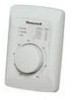
Fig. 1. H8908A,D control.
Fig. 2. H8908B,C control.
M24726
Humidity Control
Régulateur d'humidité
-20
°
F
-10
°
F
0
°
F
+10
°
F
+20
°
F
Over 20
°
F
15%
20%
25%
30%
35%
40%
HUMIDITY
SETTING
OUTDOOR
TEMPERATURE
-30
°
C
-25
°
C
-20
°
C
-10
°
C
-5
°
C
Over 0
°
C
M13371
CASE REMOVAL
SLOT
HOLE FOR WIRING
THE DUCT MOUNTING
INSTALLATIONS