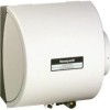
Honeywell HE260A1010 Installation Guide
Honeywell HE260A1010 - Whole House Humidifier Manual
 |
UPC - 085267207744
View all Honeywell HE260A1010 manuals
Add to My Manuals
Save this manual to your list of manuals |
Honeywell HE260A1010 manual content summary:
- Honeywell HE260A1010 | Installation Guide - Page 1
a great investment in improving the comfort of your home. APPLICATION This installation kit contains all the parts necessary to install your new Honeywell HE220 or HE260 Humidifier. INSTALLATION Preparing for the Installation Be sure to identify all the required (Table 1) accessories (included) and - Honeywell HE260A1010 | Installation Guide - Page 2
) with the humidifier solenoid valve. Locating Closest Floor Drain • Select location with access to a floor drain to provide drainage for air conditioner condensation and humidifier drainage. • If you do not have a drain available, we recommend that you install the Honeywell Whole House Drum or Disk - Honeywell HE260A1010 | Installation Guide - Page 3
interchangeable for either left or right bypass installation. To change direction, remove the screws holding each sidewall, reverse sidewall locations, and reinstall the screws. COVER SIDEWALL WATER FEED NOZZLE HUMIDIFIER PAD ASSEMBLY FRAME HUMIDIFIER HOUSING WATER FEED TUBE SHEET METAL SCREWS - Honeywell HE260A1010 | Installation Guide - Page 4
To prevent debris from clogging the solenoid inline filter, be sure to install the saddle valve handle pointing toward the ceiling. SCREW DRIVER WATER LINE M20175 M20174 Fig. 7. Connecting bypass ducting. IMPORTANT To avoid sagging and stress on humidifier, add support if ducting is longer than - Honeywell HE260A1010 | Installation Guide - Page 5
both springs attached. Be sure to select air flow direction and remove spring(s) not required for installation. M20176 Fig. 9. Installing feed tubing. 4. Connect a 1/2 in. (13 mm) drain tube to the humidifier drain fitting and run to the floor drain (see Fig. 10). a. Slide the drain clamp over - Honeywell HE260A1010 | Installation Guide - Page 6
power supply before installing or servicing equipment. IMPORTANT All wiring must comply with applicable local code, ordinances and regulations. Wire the humidifier solenoid valve, sail switch, humidistat and transformer.See Fig. 15 HUMIDISTAT Humidity Control Régulateur d'humidité OUTDOOR - Honeywell HE260A1010 | Installation Guide - Page 7
winter position). ❑ Control wiring was reviewed using circuit diagram. ❑ Transformer is plugged in. ❑ Feed line has no kinks. ❑ Drain line slopes continuously down and ends at floor drain. ❑ Water hose inside humidifier is connected to PerfectFlow™ water distribution tray. After installation use the - Honeywell HE260A1010 | Installation Guide - Page 8
2. Troubleshooting Humidifier. What to look for Leaking joints What to do Shut off water. Tighten connections. Brass tubing inserts Saddle valve leaking Electrical Humidistat Verify that brass tubing inserts are used. Verify rubber pad is installed on saddle valve. Verify control circuit wiring

® U.S. Registered Trademark
Copyright © 2001 Honeywell •
•All Rights Reserved
INSTALLATION INSTRUCTIONS
69- 1570
HE220, HE260 Humidifier
Installation Kit
WELCOME
To the comfortable world of humidified air. When you use
your Honeywell humidifier, you notice that your skin is not
as dry, and that your scratchy throat and irritated nasal
passages that aggravate allergies and asthma are
steadily improving.
You have also taken the first step in reducing the
zapping
you create when you walk on your carpet and then touch
your TV, computer, metal door knob or your pet. Your
furniture and woodwork are also benefitting from the
difference that humidified air makes.
Congratulations! You have just made a great investment
in improving the comfort of your home.
APPLICATION
This installation kit contains all the parts necessary to
install your new Honeywell HE220 or HE260 Humidifier.
INSTALLATION
Preparing for the Installation
Be sure to identify all the required (Table 1) accessories
(included) and make sure the appropriate tools are
available before beginning the installation.
Required Accessories (Included)
Required Tools
Tools required for installation include:
•
Tin snip.
•
Screwdriver.
•
Adjustable or open-end wrench.
•
Drill, punch or awl.
•
Level.
Table 1. Required Accessories.
Quantity
Accessory
6 ft (1.85M)
Bypass ducting including:
6 in. (155 mm) diameter flexible duct
Starter collar
Summer shut-off damper
Duct tape
20 ft (6.2m)
18 gauge, two-strand thermostat wire
20 ft (6.2m)
1/4 in. (6.35 mm) OD feed water tubing
10 ft (3.1m)
1/2 in (12.7 mm) ID drain tubing
1 bag
Connecting and mounting hardware:
Wire nuts (4)
No. 8 sheet metal screws (18)
Drain tube clamps (2 sizes)
Feed tube mounting clamps (6)
Brass inserts (2)
Plastic compression rings (2)
1
Plug-in transformer
1
Sail switch


