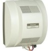
Honeywell HE360A Owners Manual
Honeywell HE360A - Whole House Powered Humidifier Manual
 |
View all Honeywell HE360A manuals
Add to My Manuals
Save this manual to your list of manuals |
Honeywell HE360A manual content summary:
- Honeywell HE360A | Owners Manual - Page 1
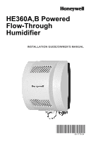
HE360A,B Powered Flow-Through Humidifier INSTALLATION GUIDE/OWNER'S MANUAL 69-1176-04 - Honeywell HE360A | Owners Manual - Page 2
HE360A,B POWERED FLOW-THROUGH HUMIDIFIER 69-1176-04 2 - Honeywell HE360A | Owners Manual - Page 3
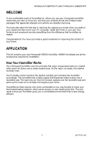
the comfort of your home. APPLICATION This kit contains your new Honeywell HE360 Humidifier, H8908 Humidistat and all the accessories required for installation. How Your Humidifier Works Your Honeywell humidifier uses the principle that vapor (evaporated water) is created when warm air blows over - Honeywell HE360A | Owners Manual - Page 4
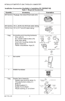
HE360A,B POWERED FLOW-THROUGH HUMIDIFIER Installation Accessories (Available in Installation Kit 32005847-00) Table 1. Required Accessories Quantity Accessory 20 ft (6.2m) 18 gauge, two-strand thermostat wire Illustration THERMOSTAT WIRE 20 ft (6.2m) 1/4 in. (6.35 mm) OD feed water tubing 10 - Honeywell HE360A | Owners Manual - Page 5
HE360A,B POWERED FLOW-THROUGH HUMIDIFIER Required Tools Tools required for installation include: • Tin snips. • Screwdriver. • Adjustable or open-end wrench. • Battery-powered Drill, punch or awl. • Level. • Work Gloves (preferably cut-resistant). • Safety Glasses. 5 69-1176-04 - Honeywell HE360A | Owners Manual - Page 6
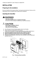
HE360A,B POWERED FLOW-THROUGH HUMIDIFIER INSTALLATION Preparing for the Installation Be sure to identify all the required (Table 1) accessories (included) and make sure the appropriate tools are available before beginning the installation. Installing the Humidifier WARNING Hazardous Voltage Can - Honeywell HE360A | Owners Manual - Page 7
that you install the Honeywell Whole House Drum or Disk Humidifier. Make sure that the 10 ft (3.1m) of drain tubing is adequate to reach from the humidifier drain connection to the floor drain. Selecting Location for Sail Switch • Select a location for the sail switch in the cold air return duct - Honeywell HE360A | Owners Manual - Page 8
the outlet. • Make sure that the 20 ft (6.2m) of thermostat wire is adequate to reach from the humidifier solenoid, to the sail switch, to the humidistat. Installing the Humidifier WARNING Hazardous Voltage Can cause personal injury or equipment damage. Do not cut or drill into any air conditioning - Honeywell HE360A | Owners Manual - Page 9
HE360A,B POWERED FLOW-THROUGH HUMIDIFIER 2. Make sure the humidifier housing is level, then position it DRAIN TUBING M20204 Fig. 4. Installing humidifier on duct. 5. Reinstall the humidifier pad assembly in the humidifier housing. IMPORTANT Be sure to reconnect the water feed tube and ensure that - Honeywell HE360A | Owners Manual - Page 10
the solenoid in-line filter, be sure to install the saddle valve handle pointing toward the ceiling. SCREW DRIVER WATER LINE M20175 Fig. 5. Installing the saddle valve. 3. Use 1/4 in. (6 mm) OD tubing and connect the saddle valve to the inlet side of the solenoid valveon the humidifier (see - Honeywell HE360A | Owners Manual - Page 11
HE360A,B POWERED FLOW-THROUGH HUMIDIFIER NOTE: To prevent leaking, use plastic (Delrin) sleeve rings with plastic tubing. Use copper sleeve rings only with copper tubing. d. Insert the tubing into the solenoid valve fitting and support the valve while tightening the compression nut. NOTE: Do not - Honeywell HE360A | Owners Manual - Page 12
HE360A,B POWERED FLOW-THROUGH HUMIDIFIER M20177 Fig. 7. Installing the drain tubing. Installing the Sail Switch Adapting Switch to Air Flow Direction The S688A Sail Switch has two counterbalancing springs in place as shown in Fig 8. These springs offset the effect of gravity for air flow direction. - Honeywell HE360A | Owners Manual - Page 13
HE360A,B POWERED FLOW-THROUGH HUMIDIFIER UP M3014 Fig. 8. Adapting sail switch to air flow direction or mounting position. • Vertical downward air flow: Leave the spring in place that is attached to the bracket marked Down. Remove the spring that is attached to the bracket marked Up. • Vertical - Honeywell HE360A | Owners Manual - Page 14
HE360A,B POWERED FLOW-THROUGH HUMIDIFIER - LOOSEN SETSCREW - INSERT SAIL CORD - TUCK CORD INTO TAB SLOTS - TIGHTEN SETSCREW SAIL M31017 Fig. 9. Attaching sail to switch. 5. Press together the sides of the wire loop. Insert the sail into the duct. (When in the Off position, the sail should point into - Honeywell HE360A | Owners Manual - Page 15
HE360A,B POWERED FLOW-THROUGH HUMIDIFIER 6. Secure the switch by using the sheet metal screws provided. 7. After wiring, snap on the cover. Installing the Humidistat Installing on Mounting Duct 1. Apply the template to the duct location chosen for the humidistat. Make sure the template is level - Honeywell HE360A | Owners Manual - Page 16
cause personal injury or equipment damage. Disconnect power supply before installing or servicing equipment. IMPORTANT All wiring must comply with applicable local code, ordinances and regulations. Wire the humidifier solenoid valve, sail switch, humidistat and transformer.See Fig. 12. HUMIDISTAT - Honeywell HE360A | Owners Manual - Page 17
HE360A,B POWERED FLOW-THROUGH HUMIDIFIER TESTING HUMIDIFIER OPERATION Checklist ‰ Humidifier is level. ‰ Control wiring was reviewed using circuit diagram. ‰ Humidifier is plugged in. ‰ Feed line has no kinks. ‰ Drain line slopes continuously down and ends at floor drain. ‰ Water hose inside - Honeywell HE360A | Owners Manual - Page 18
HE360A,B POWERED FLOW-THROUGH HUMIDIFIER Table 2. Setting Your Humidistat. When Outside Temperature is: Use This Control Setting: -20°F (-29°C) 15 -10°F (-23°C) 20 0°F (-18°C) 25 +10°F (-12°C) 30 +20°F (-7°C) 35 Above 20°F (-7°C) 40 69-1176-04 18 - Honeywell HE360A | Owners Manual - Page 19
are more difficult to clean than soft water deposits. Use the following procedure to clean your Honeywell humidifier. WARNING Serious Personal Injury Hazard. Can cause electrical shock and injury from moving parts. Disconnect power and shut off water supply before removing cover. IMPORTANT Never oil - Honeywell HE360A | Owners Manual - Page 20
sure the marked end of the pad is facing up. Place the tray on the new pad. 14. Place the humidifier pad assembly in the humidifier housing. Be sure the water feed tube is placed in the guide slots. 15. Replace the humidifier cover. 16. Verify the humidifier operation by following the steps in the - Honeywell HE360A | Owners Manual - Page 21
to click. Humidifier power Verify that outlet has power. Sail switch Remove sail cover; turn on furnace fan and listen for faint click. Verify that sail can move freely in duct; check sail switch instructions to trim sail, if necessary. Solenoid After verifying other wiring components, turn - Honeywell HE360A | Owners Manual - Page 22
HE360A,B POWERED FLOW-THROUGH HUMIDIFIER Table 3. Troubleshooting Humidifier (Continued) Problem Low humidity High humidity What to look for Furnace • blower not operating. • • • • Rapid air • changes. • Drafts (cold air • is dry and is an added load to • the humidifier). - Honeywell HE360A | Owners Manual - Page 23
HE360A,B POWERED FLOW-THROUGH HUMIDIFIER 23 69-1176-04 - Honeywell HE360A | Owners Manual - Page 24
HE360A,B POWERED FLOW-THROUGH HUMIDIFIER LIMITED ONE-YEAR WARRANTY Honeywell warrants this product, excluding humidifier pad, to be free from defects in the workmanship or materials, under normal use and service, for a period of one (1) year from the date of purchase by the consumer. If, at any time
-
 1
1 -
 2
2 -
 3
3 -
 4
4 -
 5
5 -
 6
6 -
 7
7 -
8
-
9
-
10
-
11
-
12
-
13
-
14
-
15
-
16
-
17
-
18
-
19
-
20
-
21
-
22
-
23
-
24
 |
 |

69-1176-04
HE360A,B Powered
Flow-Through
Humidifier
INSTALLATION GUIDE/OWNER’S MANUAL