Honeywell HE360A1043 Owner's Manual
Honeywell HE360A1043 Manual
 |
View all Honeywell HE360A1043 manuals
Add to My Manuals
Save this manual to your list of manuals |
Honeywell HE360A1043 manual content summary:
- Honeywell HE360A1043 | Owner's Manual - Page 1
and Installation Kit INSTALLATION INSTRUCTIONS/OWNER'S GUIDE WELCOME To the comfortable world of humidified air. When you use your Honeywell humidifier, notice that your skin is not as dry, and that your scratchy throat and irritated nasal passages that aggravate allergies and asthma are - Honeywell HE360A1043 | Owner's Manual - Page 2
humidifier drainage. • If you do not have a drain available, we recommend that you install the Honeywell Whole House Drum or Disk Humidifier. duct from the air entrance. (See Fig. 1-3 in S688 Installation Instructions.) Selecting Location for Humidistat • Select a location for the humidistat on the - Honeywell HE360A1043 | Owner's Manual - Page 3
the thumbscrew located at the bottom of the cover. Connecting the Plumbing Use hot or cold water and either hard or softened water in the humidifier. 1. Shut off the water. CAUTION Chemical Hazard. Can cause personal injury or equipment damage. Do not use any line connected to an air conditioner. Do - Honeywell HE360A1043 | Owner's Manual - Page 4
tubing and connect the saddle valve to the inlet side of the solenoid valveon the humidifier (see Fig. 7). a. Place the brass compression nut over the tubing. b. Install . d. Insert the tubing into the solenoid valve fitting and support the valve while tightening the compression nut. NOTE: Do not - Honeywell HE360A1043 | Owner's Manual - Page 5
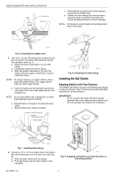
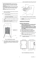
marked Down. • Horizontal air flow: Remove both springs. HE360 HUMIDIFIER AND INSTALLATION KIT AIRFLOW 1. Mount the template (provided with the H8908 case. See Fig. 12. NOTE: For wall mounting instructions, see the H8908 Installation Instructions. Fig. 10. Attaching sail to switch. 5. Press - Honeywell HE360A1043 | Owner's Manual - Page 6
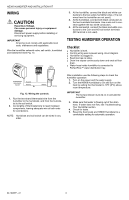
or servicing equipment. IMPORTANT All wiring must comply with applicable local code, ordinances and regulations. Wire the humidifier solenoid to activate the humidifier. 3. Make sure that water is flowing out of the drain hose. If water does not flow, see Troubleshooting Your Humidifier section. 4. - Honeywell HE360A1043 | Owner's Manual - Page 7
, but hard water mineral deposits are more difficult to clean than soft water deposits. Use the following procedure to clean your Honeywell humidifier. WARNING Serious Personal Injury Hazard. Can cause electrical shock and injury from moving parts. Disconnect power and shut off water supply - Honeywell HE360A1043 | Owner's Manual - Page 8
tube is placed in the guide slots. 15. Replace the humidifier cover. 16. Verify the humidifier operation by following the steps in the Checking Your Humidifier for Correct Operation section. CHECKING YOUR HUMIDIFIER FOR CORRECT OPERATION After winter startup or servicing, use the following steps to - Honeywell HE360A1043 | Owner's Manual - Page 9
TROUBLESHOOTING YOUR HUMIDIFIER HE360 HUMIDIFIER AND INSTALLATION KIT Problem Water leakage No water to drain. Low humidity High humidity Table 3. Troubleshooting Humidifier sail can move freely in duct; check sail switch instructions to trim sail, if necessary. Solenoid After verifying other - Honeywell HE360A1043 | Owner's Manual - Page 10
AND INSTALLATION KIT LIMITED ONE-YEAR WARRANTY Honeywell warrants this product, excluding humidifier pad, to be free from defects in the workmanship or materials, under normal use and service, for a period of one (1) year from the date of purchase by the consumer. If, at any time during the - Honeywell HE360A1043 | Owner's Manual - Page 11
HE360 HUMIDIFIER AND INSTALLATION KIT 11 69-1646EF-01 - Honeywell HE360A1043 | Owner's Manual - Page 12
HE360 HUMIDIFIER AND INSTALLATION KIT Automation and Control Solutions Honeywell Honeywell Limited-Honeywell Limitée 1985 Douglas Drive North 35 Dynamic Drive Golden Valley, MN 55422 Scarborough, Ontario M1V 4Z9 69-1646EF-01 E.K. 06-09 Printed in U.S.A. on recycled - Honeywell HE360A1043 | Owner's Manual - Page 13
Humidificateurs HE360 et trousse d'installation INSTRUCTIONS D'INSTALLATION/MANUEL DU PROPRIÉTAIRE BIENVENUE... dans un environnement tout confort, où l'air est humidifié. Avec votre humidificateur Honeywell, vous constaterez que votre peau sera moins sèche. Vous remarquerez aussi, de jour en jour - Honeywell HE360A1043 | Owner's Manual - Page 14
il est préférable d'installer l'humidificateur central à tambour ou à disque de Honeywell. S'assurer que le tuyau de vidange de 3,1 m (10 pi) flux d'air dans la gaine. (Voir les Fig. 1-3, dans les Instructions d'installation du S688.) Choix de l'emplacement de l'humidistat • Installer l'humidistat - Honeywell HE360A1043 | Owner's Manual - Page 15
HUMIDIFICATEURS HE360 ET TROUSSE D'INSTALLATION Repérage de la prise électrique 120 V la plus près • Choisir un endroit près d'une prise. S'il n'y a pas de prise, en faire installer une par un électricien. • S'assurer que le cordon de l'humidificateur est suffisamment long et qu'il peut être branch - Honeywell HE360A1043 | Owner's Manual - Page 16
HUMIDIFICATEURS HE360 ET TROUSSE D'INSTALLATION Raccordement des tuyaux L'humidificateur fonctionne avec de l'eau chaude ou de l'eau froide et avec de l'eau dure ou de l'eau douce. 1. Fermer le robinet d'arrêt. MISE EN GARDE Produits chimiques dangereux. Peut causer des blessures ou des dommages - Honeywell HE360A1043 | Owner's Manual - Page 17
marqué «Up» • Courant d'air vertical, vers le haut : Laisser en place le ressort attaché au support marqué «Up». Enlever le support attaché au support marqué «Down». • Courant d'air horizontal : Enlever les deux ressorts. 1. Placer le gabarit fourni avec l'interrupteur à ailette à l'endroit choisi - Honeywell HE360A1043 | Owner's Manual - Page 18
les trous. 2. Utiliser le gabarit fourni avec les instructions d'installation de l'humidistat H8908 pour percer l'ouverture pour ¡F Over 0 ¡C HUMIDITY SETTING 15% 20% 25% 30% 35% 40% SAIL SWITCH HUMIDIFIER SOLENOID VALVE BLACK WHITE WHITE M20205 69-1646EF-01 Fig. 13. Câblage des appareils. 1. - Honeywell HE360A1043 | Owner's Manual - Page 19
qui sort de l'appareil de chauffage passe sur l'écran évaporateur de l'humidificateur et capte l'air humide pour le faire circuler dans la maison. L'air humidifié est plus chaud et il assure un meilleur confort. Le point de consigne du thermostat peut donc être abaissé, ce qui permet de diminuer - Honeywell HE360A1043 | Owner's Manual - Page 20
HUMIDIFICATEURS HE360 ET TROUSSE D'INSTALLATION AVERTISSEMENT Risque de blessures graves. Les pièces mobiles peuvent causer des chocs électriques ou des blessures. Couper l'alimentation électrique et fermer l'arrivée d'eau avant d'enlever le couvercle. IMPORTANT Ne jamais lubrifier les pièces de l' - Honeywell HE360A1043 | Owner's Manual - Page 21
s'il y a un déclic. Vérifier si l'interrupteur de l'ailette bouge facilement dans la gaine; s'il y a lieu, tailler l'ailette en suivant les instructions. Électrovanne Vérifier les autres éléments de câblage, puis mettre en marche le ventilateur de l'appareil de chauffage, abaisser et augmenter le - Honeywell HE360A1043 | Owner's Manual - Page 22
ne couvre pas les frais d'installation et de retrait de ce produit. La présente garantie ne s'appliquera pas s'il est démontré par Honeywell que la défectuosité ou le mauvais fonctionnement du produit est attribuable à un endommagement du produit alors que le consommateur l'avait en sa possession - Honeywell HE360A1043 | Owner's Manual - Page 23
HUMIDIFICATEURS HE360 ET TROUSSE D'INSTALLATION 11 69-1646EF-01 - Honeywell HE360A1043 | Owner's Manual - Page 24
HUMIDIFICATEURS HE360 ET TROUSSE D'INSTALLATION Solutions de régulation et d'automatisation Honeywell Honeywell Limited-Honeywell Limitée 1985 Douglas Drive North 35, Dynamic Drive Golden Valley, MN 55422 Scarborough (Ontario) M1V 4Z9 69-1646EF-01 E.K. 06-09 Imprimé aux États-Unis
-
 1
1 -
 2
2 -
 3
3 -
 4
4 -
 5
5 -
 6
6 -
 7
7 -
8
-
9
-
10
-
11
-
12
-
13
-
14
-
15
-
16
-
17
-
18
-
19
-
20
-
21
-
22
-
23
-
24
 |
 |

® U.S. Registered Trademark
Copyright © 2002 Honeywell •
•All Rights Reserved
INSTALLATION INSTRUCTIONS/OWNER’S GUIDE
69-1646EF-01
HE360 Humidifier and
Installation Kit
WELCOME
To the comfortable world of humidified air. When you use
your Honeywell humidifier, notice that your skin is not as
dry, and that your scratchy throat and irritated nasal
passages that aggravate allergies and asthma are
steadily improving.
You have also taken the first step in reducing the
zapping
you create when you walk on your carpet and then touch
your TV, computer, metal door knob or your pet. Your
furniture and woodwork are also benefitting from the
difference that humidified air makes.
Congratulations! You have just made a great investment
in improving the comfort of your home.
APPLICATION
This kit contains your new Honeywell HE360 Humidifier,
H8908 Humidistat and all the accessories required for
installation.
INSTALLATION
Preparing for the Installation
Be sure to identify all the required (Table 1) accessories
(included) and make sure the appropriate tools are
available before beginning the installation.
Required Accessories (Included)
Required Tools
Tools required for installation include:
•
Tin snip.
•
Screwdriver.
•
Adjustable or open-end wrench.
•
Drill, punch or awl.
•
Level.
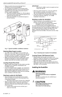
Determining Best Location for Humidifier
CAUTION
Temperature and Static Pressure Hazard.
Can cause property or equipment damage.
Locate humidifier where ambient temperature is
between 32°F (0°C) and 160°F (71°C).
Do not install humidifier where freezing
temperatures could occur.
Be sure supply plenum static pressure is no
greater than 0.4 in. wc and water pressure is no
greater than 124 psi.
•
Select a location for the humidifier on the supply
(warm air stream) plenum. See Fig. 1.
Table 1. Required Accessories.
Quantity
Accessory
20 ft (6.2m)
18 gauge, two-strand thermostat wire
20 ft (6.2m)
1/4 in. (6.35 mm) OD feed water tubing
10 ft (3.1m)
1/2 in (12.7 mm) ID drain tubing
1 bag
Connecting and mounting hardware:
Wire nuts (4)
No. 8 sheet metal screws (18)
Drain tube clamp
Feed tube mounting clamps (6)
Brass inserts (2)
Plastic compression rings (2)
1
Sail switch
1
H8908 Humidistat
1 bag
Saddle Valve Assembly:
Saddle valve and top clamp (1)
Threaded bottom clamp (1)
Bolts (2)
Rubber gasket (1)
Eyelet (1)
Plastic bushing (1)
Table 1. Required Accessories.
Quantity
Accessory