Honeywell HP400ULM Installation Instructions
Honeywell HP400ULM Manual
 |
View all Honeywell HP400ULM manuals
Add to My Manuals
Save this manual to your list of manuals |
Honeywell HP400ULM manual content summary:
- Honeywell HP400ULM | Installation Instructions - Page 1
HP400ULM is a 12VDC or 24VDC power supply with an HPMOM6 distribution controller to be used with Card Access Systems. It provides 12/24VDC through 6 power-limited outputs. The 6 outputs will switch ON or OFF security Fail safe dry contact output for Battery trouble (Fail Safe). 11. Battery polarity - Honeywell HP400ULM | Installation Instructions - Page 2
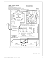
- Red LED for power on indication. • Fire Alarm Control Panel Input - Polarity Instructions 1. Mounting The power supply should be installed in accordance with all Governing National Electrical and Local Codes. Mount the power supply securely HP400ULM Installation Document P/N 52390:A 1/05/06 - Honeywell HP400ULM | Installation Instructions - Page 3
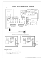
the 2.2K Ohm (EOL) resistor provided at a Key Switch or Push Button to perform this manual reset operation and to supervise this connection as shown in Fig 1a. 6. Alarm/Trouble Output a) Power Fail: When DC Power fails or PTC activates this will cause the dry contact "Form C" relay to de-energize - Honeywell HP400ULM | Installation Instructions - Page 4
touch non-power limited wiring; minimum spacing 1/4". Installation and servicing should only be made by qualified personnel; contains no user-serviceable parts. Install in accordance with all local regulations and the National Electrical Code. Continued on next page... 4 HP400ULM Installation - Honeywell HP400ULM | Installation Instructions - Page 5
HP400ULM Installation Document P/N 52390:A 1/05/06 Continued on next page... 5 - Honeywell HP400ULM | Installation Instructions - Page 6
For additional information: • Visit our website at http://www.honeywellpower.com • Contact Technical Support at 1(877) HPP-POWR • E-mail us at [email protected] 6 HP400ULM Installation Document P/N 52390:A 1/05/06
-
 1
1 -
 2
2 -
 3
3 -
 4
4 -
 5
5 -
 6
6
 |
 |

HP400ULM
Access Control Power Supply/Charger
with Power Distribution Controller
PN 52390:A
1/05/06
ECN 04-350
Honeywell
12 Clintonville Road
Northford, CT 06472
Product Installation Document
This product follows under the UL1481 Fire Alarm Systems, UL603 Burglary Alarm Systems and UL294 Access Control
Systems. The HP400ULM unit is to be installed in a fail safe mode unless authorized by the local AHJ. This product must
be installed in compliance with Article 760 of the National Electrical Code, NFPA70, as well as NFPA72 National Fire
Alarm Code and all applicable local codes.
1 Description
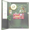
The HP400ULM is a 12VDC or 24VDC power supply with an HPMOM6 distribution controller to be used with Card
Access Systems. It provides 12/24VDC through 6 power-limited outputs. The 6 outputs will switch ON or OFF security
devices such as Magnetic Locks, Door Strikes, Magnetic Fire Door Holders, etc. The HPMOM6 offers a choice of two (2)
outputs, “Fail Safe or Fail Secure” and a choice of two (2) Fire inputs, N/O or N/C, and Reverse Polarity triggered by the
FACP. The Controller also has 2 Trouble/ Alarm dry contact outputs type “Form C”; 1) Power Fail/ PTC Activated, and 2)
FACP Triggered. The unit has not been evaluated as elevator equipment, and is not authorized for bell output in
Mercantile applications.
2 Specifications
A) Power Supply Board
1.
Input voltage: 120VAC 60Hz; Current: 2.50A max.
2.
Output Voltage: 12VDC or 24VDC, jumper selectable; Current: 4.0A continuous output maximum, 3.5A plus battery
charger (not supervised).
3.
Fail safe dry contact output on AC Failure (within one minute).
4.
Built-in charger for sealed lead acid or gel cell type batteries.
5.
Instantaneous transfer to stand-by battery on AC failure.
6.
Battery presence detection (within 1 minute)
7.
Battery low disconnect at 9.90VDC or 19.90VDC.
8.
High voltage disconnect at 15VDC or 30VDC.
9.
Yellow LED (L3) indication for battery disconnected and battery low.
10.
Fail safe dry contact output for Battery trouble (Fail Safe).
11.
Battery polarity reversal protection.
12.
Thermal overload and short circuit protection.
13.
DC output PTC activated indication by Red LED (L2).
14.
DC output failure indication by Red LED ( L4 ).
15.
AC presence indication by Green LED ( L1 ).
16.
DC output indication by Red LED ( L5 ).
17.
Battery Leads included.
18.
Power Board Dimensions: 6.2”L x 4.7”W x 2.5”H.
19.
Enclosure Dimension: 17”L x 13.5”W x 4.75”H.
Accommodates two 12 Volt 12AH batteries. When using larger
batteries, a UL approved enclosure must be used.
B) Distribution Controller Board
•
Outputs
–
6 Fail Safe or Fail Secure
Continued on next page...