Honeywell HPFF12 Operation Manual - Page 13
LED Indicators, 1.6 Specifications
 |
View all Honeywell HPFF12 manuals
Add to My Manuals
Save this manual to your list of manuals |
Page 13 highlights
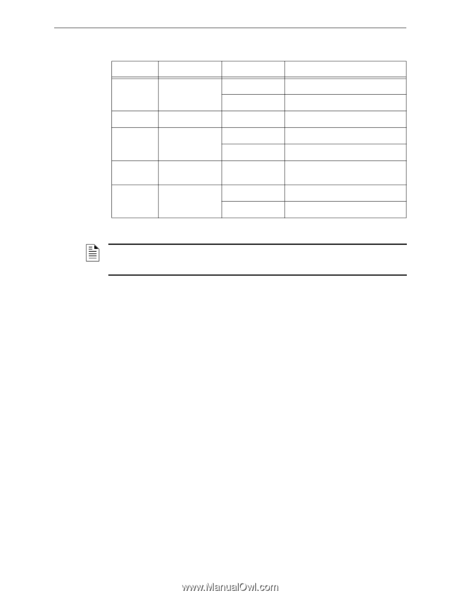
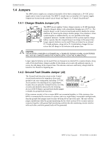
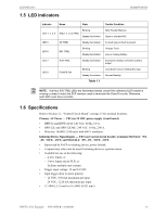
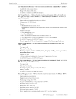
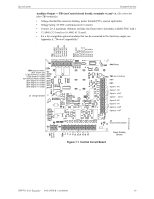
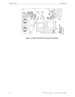
LED Indicators 1.5 LED Indicators System Overview Indicator Name State LED 1, 2, 3, 4 SIG(1, 2, 3, 4) TRBL Blinking Steady illumination LED 5 GF TRBL Steady illumination LED 6 BAT TRBL Blinking Steady illumination LED 7 AUX TRBL Steady illumination LED 8 POWER ON Blinking Steady illumination Table 1.1 Trouble Condition NAC Trouble Memory Open or shorted NAC An earth ground fault is present Charger Fault Low or missing battery Excessive loading or shorted auxiliary output Low (brown-out) or missing AC input Normal/Standby NOTE: If all four SIG TRBL LEDs are illuminated steady, check if the reference ELR resistor is missing or doesn't match the ELR resistors used to terminate the Class B circuits. Otherwise, each NAC must have a trouble. 1.6 Specifications Refer to Section 1.1, "Control Circuit Board", on page 15 for terminal locations. Primary AC Power - TB1 (on 24 VDC power-supply circuit board) • HPFF12 and HPFF12CM: 120 VAC, 60 Hz, 5.0 A. • HPFF12E and HPFF12CME: 240 VAC, 50 Hz, 2.80 A. • Wire size: 14AWG (2.08 mm²) with 600 V insulation. Initiating Device Signal Inputs - TB3 (on Control circuit board); terminals SIGNAL1: +IN, -IN, +OUT, -OUT, and SIGNAL2: +IN, -IN, +OUT, -OUT. • Supervised by FACP or initiating device, power-limited. • A supervisory relay must be used if initiating device is a power source. • Available for one of the following: - 4-wire inputs; or - 2-wire inputs and an ELR; or - facilitate multiple unit systems. • Trigger input voltage: 12 and 24 VDC. • Input trigger draw in alarm polarity: - 12 VDC, 5.68 mA maximum per input. - 24 VDC, 12.26 mA maximum per input. • 12 AWG (3.31 mm²) to 18 AWG (0.821 mm²). HPFF12 NAC Expander - P/N 53576:B 11/24/2010 13
-
 1
1 -
2
-
3
-
4
-
5
-
6
-
7
-
 8
8 -
 9
9 -
 10
10 -
 11
11 -
 12
12 -
 13
13 -
 14
14 -
 15
15 -
 16
16 -
 17
17 -
 18
18 -
19
-
20
-
21
-
22
-
23
-
24
-
25
-
26
-
27
-
28
-
29
-
30
-
31
-
32
-
33
-
34
-
35
-
36
-
37
-
38
-
39
-
40
-
41
-
42
-
43
-
44
-
45
-
46
-
47
-
48
-
49
-
50
-
51
-
52
-
53
-
54
-
55
-
56
-
57
-
58
-
59
-
60
-
61
-
62
-
63
-
64
 |
 |