Honeywell HPFF12 Operation Manual - Page 15
Control Circuit Board
 |
View all Honeywell HPFF12 manuals
Add to My Manuals
Save this manual to your list of manuals |
Page 15 highlights
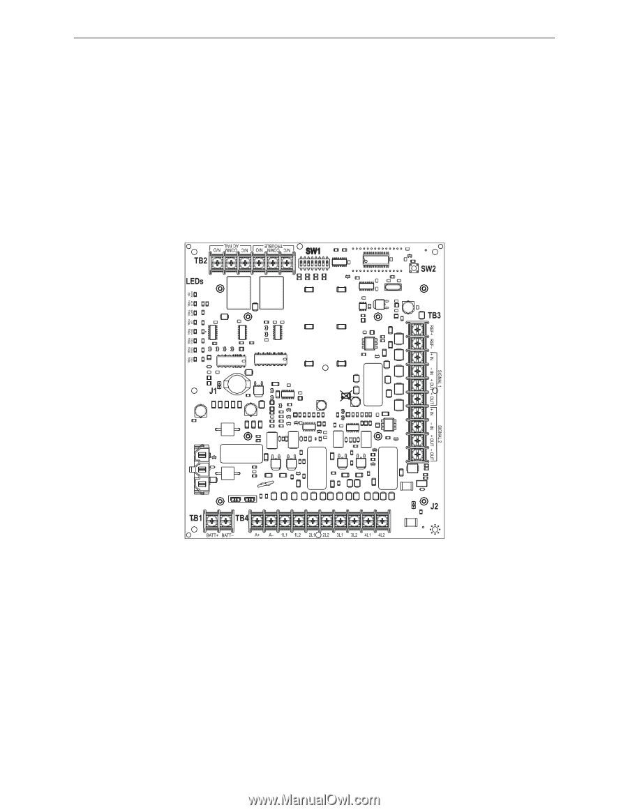
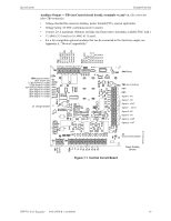
Specifications System Overview Auxiliary Output - TB4 (on Control circuit board); terminals +A and -A. (See above for other TB4 terminals.) • Voltage checked for excessive loading, power limited (PTC), special application. • Voltage rating: 24 VDC continuous (even in alarm). • Current: 2.0 A maximum. (Subtract auxiliary load from total to determine available NAC load.) • 12 AWG (3.31 mm²) to 18 AWG (0.75 mm²). • For a list compatible optional modules that can be connected to the Auxiliary output, see Appendix A, "Device Compatibility". g TB2 (left to right): AC Fail N/O AC Fail COMM AC Fail N/C Trouble N/O' Trouble COMM Trouble N/C SW1 (left to right): SIG SEL AC 2 HR SYN SEL 'B' SYN SEL 'A' SIG 3/4 'B' SIG 3/4 'A' SIG 1/2 'B' SIG 1/2 'A' LEDs (top to bottom): LED1 (Power On) LED2 (Auxiliary Trouble) LED3 (Battery Trouble) ED4 (Ground Fault Trouble) LED5 (Signal 4 Trouble) LED6 (Signal 3 Trouble) LED7 (Signal 2 Trouble) LED8 (Signal 1 Trouble) J1 Charger Disable g SW2 Reset TB3 (top to bottom): REF+ REF- Signal 1 +IN Signal 1 -IN Signal 1 +OUT Signal 1 -OUT) Signal 2 +IN Signal 2 -IN Signal 2 +OUT Signal 2 -OUT J2: Ground Fault Disable Figure 1.1 Control Circuit Board Alarm Polarity Shown TB1: BATT- BATT+ TB4: A+ A- 1L1 1L2 2L1 2L2 3L1 3L2 4L1 4L2 HPFF812PCA.cdr HPFF12 NAC Expander - P/N 53576:B 11/24/2010 15
-
 1
1 -
2
-
3
-
4
-
5
-
6
-
7
-
8
-
9
-
 10
10 -
 11
11 -
 12
12 -
 13
13 -
 14
14 -
 15
15 -
 16
16 -
 17
17 -
 18
18 -
 19
19 -
 20
20 -
21
-
22
-
23
-
24
-
25
-
26
-
27
-
28
-
29
-
30
-
31
-
32
-
33
-
34
-
35
-
36
-
37
-
38
-
39
-
40
-
41
-
42
-
43
-
44
-
45
-
46
-
47
-
48
-
49
-
50
-
51
-
52
-
53
-
54
-
55
-
56
-
57
-
58
-
59
-
60
-
61
-
62
-
63
-
64
 |
 |