Honeywell HPFF12 Operation Manual - Page 17
Installation, 2.1 Backbox Mounting
 |
View all Honeywell HPFF12 manuals
Add to My Manuals
Save this manual to your list of manuals |
Page 17 highlights
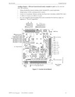
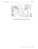
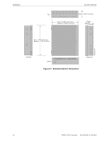
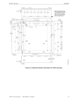
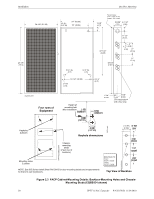
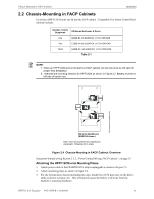
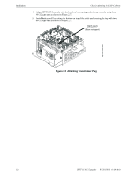
Section 2: Installation The standard cabinet may be either semi-flush or surface mounted. Fire Alarm Control Panel (FACP) cabinets can only be wall mounted. Each cabinet mounts using two or three key slots and two 0.250" (6.35 mm) diameter holes in the backbox. The key slots are located at the top of the backbox and the two securing holes at the bottom. Carefully unpack the system and check for shipping damage. Mount the cabinet in a clean, dry, vibration-free area where extreme temperatures are not encountered. The area should be readily accessible with sufficient room to easily install and maintain the panel. Locate the top of the cabinet approximately 5 feet (1.5 m) above the floor with hinge mounting on the left. Determine the number of conductors required for the devices to be installed. Sufficient knockouts are provided for wiring convenience. Select the appropriate knockout(s) and pull the conductors into the box. All wiring should be in accordance with the National and/or Local codes for fire alarm systems and power supplies. 2.1 Backbox Mounting ! CAUTION: THE CIRCUIT BOARD CONTAINS STATIC-SENSITIVE COMPONENTS. ALWAYS GROUND YOURSELF WITH A STATIC STRAP BEFORE HANDLING ANY BOARDS SO THAT THE STATIC CHARGES ARE REMOVED FROM THE BODY. USE STATIC SUPPRESSIVE PACKAGING TO PROTECT ELECTRONIC ASSEMBLIES. To prevent damage to the circuit board and to facilitate backbox mounting, the chassis with the 24 VDC power supply and the Control circuit board can be easily removed. Loosen the two #8-32 nuts securing the top flanges of the chassis, then slide the chassis up to free it from the lower tabs. Place the chassis assembly in a safe location until it can be reinstalled in the backbox. 1. Mark and predrill a hole in the wall for the center top keyhole mounting bolt using the dimensions illustrated in Figure 2.2, "Standard Cabinet: Dimensions for Wall-mounting" on page 19 or Figure 2.3, "FACP Cabinet-Mounting Details: Backbox-Mounting Holes and Chassis-Mounting Studs (EQBB-D4 shown)" on page 20. NOTE: See EQ Series Install Sheet PN 53412 for door-mounting details and measurements for B-size and C-size backboxes. 2. Install the center top fastener in the wall with screw head protruding. 3. Place backbox over the top screw, level and secure. 4. Mark and drill the left and right upper and lower mounting holes. 5. Note: outer holes (closest to sidewall) are used for 16" O.C. stud mounting. 6. Install remaining fasteners. HPFF12 NAC Expander - P/N 53576:B 11/24/2010 17
-
 1
1 -
2
-
3
-
4
-
5
-
6
-
7
-
8
-
9
-
10
-
11
-
 12
12 -
 13
13 -
 14
14 -
 15
15 -
 16
16 -
 17
17 -
 18
18 -
 19
19 -
 20
20 -
 21
21 -
 22
22 -
23
-
24
-
25
-
26
-
27
-
28
-
29
-
30
-
31
-
32
-
33
-
34
-
35
-
36
-
37
-
38
-
39
-
40
-
41
-
42
-
43
-
44
-
45
-
46
-
47
-
48
-
49
-
50
-
51
-
52
-
53
-
54
-
55
-
56
-
57
-
58
-
59
-
60
-
61
-
62
-
63
-
64
 |
 |