Honeywell HPFF12 Operation Manual - Page 27
Two NACs Con d for Class A (Style Z), Two NACs in Class A Style Z
 |
View all Honeywell HPFF12 manuals
Add to My Manuals
Save this manual to your list of manuals |
Page 27 highlights
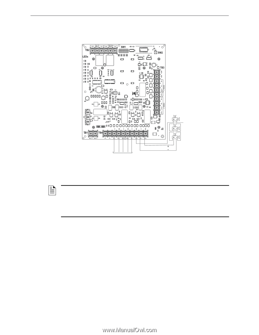
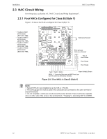
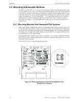
NAC Circuit Wiring 2.3.2 Two NACs Configured for Class A (Style Z) Figure 2.11 shows two NACs configured for Class A (Style Z). • Trouble on NAC1 will illuminate LED1 SIG1 TRBL and LED2 SIG2 TRBL • Trouble on NAC2 will illuminate LED3 SIG3 TRBL and LED4 SIG4 TRBL Installation HPFF12NACClassA.wmf Horn Strobe Horn Strobe Horn Strobe NAC 1 Note: NAC 1 Class A wired same as NAC2. NAC 2 Note: NAC 2 in Class A; no ELR required. Figure 2.11 Two NACs in Class A (Style Z) Alarm Polarity Shown NOTE: 1. Typical ELR's for new installations can be 3.9k or 4.7k ohm. 2. The same gauge wire must be used if two conductors are connected to the same terminal of any terminal block. 3. Do not complete a continuous circuit around the screw terminal. There must be two separate wires on either side of the screw at the terminal block. "T-tapping" is absolutely NOT ALLOWED. HPFF12 NAC Expander - P/N 53576:B 11/24/2010 27
-
 1
1 -
2
-
3
-
4
-
5
-
6
-
7
-
8
-
9
-
10
-
11
-
12
-
13
-
14
-
15
-
16
-
17
-
18
-
19
-
20
-
21
-
 22
22 -
 23
23 -
 24
24 -
 25
25 -
 26
26 -
 27
27 -
 28
28 -
 29
29 -
 30
30 -
 31
31 -
 32
32 -
33
-
34
-
35
-
36
-
37
-
38
-
39
-
40
-
41
-
42
-
43
-
44
-
45
-
46
-
47
-
48
-
49
-
50
-
51
-
52
-
53
-
54
-
55
-
56
-
57
-
58
-
59
-
60
-
61
-
62
-
63
-
64
 |
 |