Honeywell HPFF12 Operation Manual - Page 35
Programming Options, 3.1 DIP Switch Settings
 |
View all Honeywell HPFF12 manuals
Add to My Manuals
Save this manual to your list of manuals |
Page 35 highlights
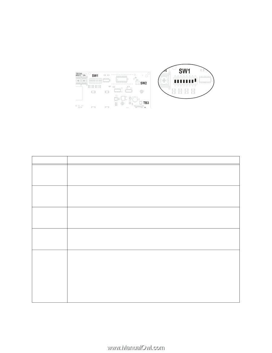
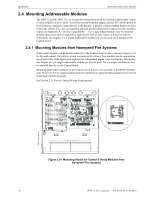
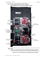
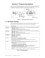
Section 3: Programming Options This section describes the programming options available via DIP switch settings. The HPFF can be field-programmed using DIP switch SW1 on the Control circuit board. Refer to the following illustration for switch location and DIP switch settings for ON and OFF positions. Switches 2-7 shown in OFF position HPFF812-sw1.wmf Switch 1 shown in ON position Figure 3.1 Field-Programming DIP Switches 3.1 DIP Switch Settings The following table lists the programmable features and the switch settings required to select a particular feature. A detailed description of each is presented in the following pages. 1 SIG 1/2 "A" 2 SIG 1/2 "A" 3 SIG 3/4 "B" 4 SIG 3/4 "B" 5 SYN SEL "B" 6 SYN SEL "A" 7 AC 2HR 8 SIG SEL SW1 DIP Switch 1 OFF, 2 OFF = Pass-through (of Steady On, sync, or coded; DO NOT use with full-wave rectified input). 1 ON, 2 OFF = Temporal. 1 OFF, 2 ON = Sync generator (see switches 5 & 6). 1 ON, 2 ON = Pass-through Filtered (use for full-wave rectified inputs). 3 OFF, 4 OFF = Pass-through (of Steady On, sync, or coded; DO NOT use with full-wave rectified input). 3 ON, 4 OFF = Temporal. 3 OFF, 4 ON = Sync generator (see switches 5 & 6). 3 ON, 4 ON = Pass-through Filtered (use for full-wave rectified inputs). 5 OFF, 6 OFF = Cooper Wheelock 5 ON, 6 OFF = System Sensor 5 OFF, 6 ON = Amseco and Faraday 5 ON, 6 ON = Gentex OFF - No delay in Trouble reporting with an AC failure. ON - 2 hour delay in Trouble reporting with an AC failure. See Sections 3.2.3 and 3.2.4 for further details of TB2 immediate AC Fail and programmed no delay/delayed Trouble contacts. This switch works in conjunction with the initiating device signal input(s) and switches 1 through 6 to determine General Alarm*, Split Alarm**, or Silencing***. 8 ON = Split Alarm** • NAC outputs 1 and 2 are controlled by Signal Input 1. • NAC outputs 3 and 4 are controlled by Signal Input 2. 8 OFF, Signal Input 1 ON, Signal Input 2 ON = General Alarm* on all four NAC outputs. 8 OFF, Signal Input 1 ON, Signal Input 2 OFF = Silencing*** of all four NAC outputs. *General Alarm is visual strobe and audible horn activation. **Split Alarm is Signal Input I controlling NAC outputs 1 and 2, and Signal Input 2 controlling NAC outputs 3 and 4. ***Silencing is visual strobe activation but audible horn is silenced for the initiating device. Table 3.1 DIP Switch Settings HPFF12 NAC Expander - P/N 53576:B 11/24/2010 35
-
 1
1 -
2
-
3
-
4
-
5
-
6
-
7
-
8
-
9
-
10
-
11
-
12
-
13
-
14
-
15
-
16
-
17
-
18
-
19
-
20
-
21
-
22
-
23
-
24
-
25
-
26
-
27
-
28
-
29
-
 30
30 -
 31
31 -
 32
32 -
 33
33 -
 34
34 -
 35
35 -
 36
36 -
 37
37 -
 38
38 -
 39
39 -
 40
40 -
41
-
42
-
43
-
44
-
45
-
46
-
47
-
48
-
49
-
50
-
51
-
52
-
53
-
54
-
55
-
56
-
57
-
58
-
59
-
60
-
61
-
62
-
63
-
64
 |
 |