Honeywell HPFF12 Operation Manual - Page 36
Programmable Features, 3.2.1 Input/Output Functions
 |
View all Honeywell HPFF12 manuals
Add to My Manuals
Save this manual to your list of manuals |
Page 36 highlights
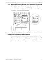
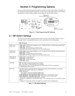
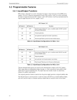
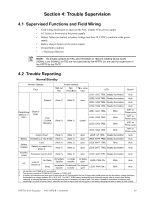
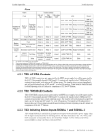
Programming Options Programmable Features 3.2 Programmable Features 3.2.1 Input/Output Functions DIP switches 1 through 4 are used to determine the input to output functions of the HPFF power supplies. The NAC outputs are programmed in pairs. DIP switches 1 and 2 are used to determine the input to output functions for NAC outputs 1 and 2. DIP switches 3 and 4 are used determine the input to output functions for NAC outputs 3 and 4. NAC Outputs 1 & 2 DIP Switch 1 DIP Switch 2 Function OFF OFF Pass-through (of Steady On, sync, or audible coded; DO NOT use with full-wave rectified input). ON OFF Temporal generator. OFF ON Sync generator (see Synchronization Type below). ON ON Pass-through Filtered (use for full-wave rectified inputs). Table 3.2 Input/Output Configurations for NACs 1 & 2 NAC Outputs 3 & 4 DIP Switch 3 DIP Switch 4 Function OFF OFF Pass-through (of Steady On, sync, or audible coded; DO NOT use with full-wave rectified input). ON OFF Temporal generator. OFF ON Sync generator (see Synchronization Type below). ON ON Pass-through Filtered (use for full-wave rectified inputs). Table 3.3 Input/Output Configurations for NACs 3 & 4 The pass-through feature passes any signal on the initiating device inputs to the NAC outputs. These signal inputs are independent in pass-through, so visual sync protocol and audible coded signals may be passed simultaneously. The signal types may include steady-on, march time, temporal or audible coded signals. The temporal generator feature is used to have the power supply generate a temporal audible code. The filtered feature is used to provide a steady-on output with full-wave rectified unfiltered input, and can be used to reduce or eliminate spurious outputs that are caused by noise on the inputs. 36 HPFF12 NAC Expander - P/N 53576:B 11/24/2010
-
 1
1 -
2
-
3
-
4
-
5
-
6
-
7
-
8
-
9
-
10
-
11
-
12
-
13
-
14
-
15
-
16
-
17
-
18
-
19
-
20
-
21
-
22
-
23
-
24
-
25
-
26
-
27
-
28
-
29
-
30
-
 31
31 -
 32
32 -
 33
33 -
 34
34 -
 35
35 -
 36
36 -
 37
37 -
 38
38 -
 39
39 -
 40
40 -
 41
41 -
42
-
43
-
44
-
45
-
46
-
47
-
48
-
49
-
50
-
51
-
52
-
53
-
54
-
55
-
56
-
57
-
58
-
59
-
60
-
61
-
62
-
63
-
64
 |
 |
