Honeywell HPFF12 Operation Manual - Page 37
Synchronization Type, 3.2.3 Trouble Reporting Delay with an AC Failure, Table 3.4
 |
View all Honeywell HPFF12 manuals
Add to My Manuals
Save this manual to your list of manuals |
Page 37 highlights
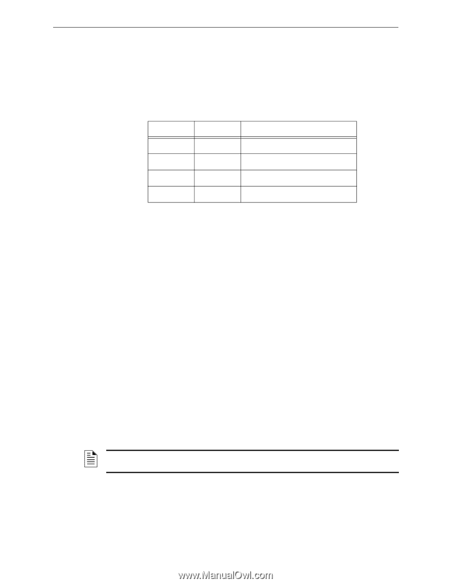
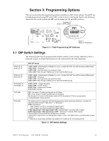
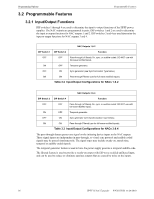
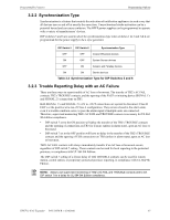
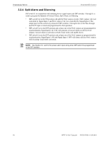
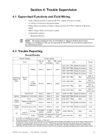
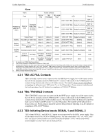
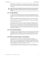
Programmable Features Programming Options 3.2.2 Synchronization Type Synchronization is a feature that controls the activation of notification appliances in such a way that all devices turn on and off at exactly the same time. Unsynchronized strobe activation can be a potential hazard and can cause confusion. The HPFF power supplies can be programmed to operate with a variety of manufacturers' devices. DIP switches 5 and 6 are used to select the synchronization type when switches 1 & 2 and 3 & 4 are programmed for the power supply to be a sync generator. DIP Switch 5 DIP Switch 6 Synchronization Type OFF OFF Cooper Wheelock devices ON OFF System Sensor devices OFF ON Amseco and Faraday devices ON ON Gentex devices Table 3.4 Synchronization Type for DIP Switches 5 and 6 3.2.3 Trouble Reporting Delay with an AC Failure There are three ways to report trouble of AC loss or brownout. The transfer of TB2's AC FAIL contacts, TB2's TROUBLE contacts, and the opening of the FACP or initiating device SIGNAL 1's and SIGNAL 2's connections on TB3. Both SIGNAL 1's and SIGNAL 2's +IN to +OUT connections are opened to disconnect Class B ELR's or the positive wire run of Class A configuration. They remain closed in the alarm state, even if a trouble condition exists, to pass the alarm signal if multiple units are connected. Therefore, supervised monitoring TB2's AC FAIL and TROUBLE contacts is necessary for UL 864 9th Edition compliance. • DIP switch 7 set to the ON position will delay the transfer of the TB2's TROUBLE contacts and the opening of connections on TB3 for 2 hours (unless in alarm state), upon an AC loss or brownout. • DIP switch 7 set to the OFF position will have no delay in the transfer of the TB2's TROUBLE contacts and the opening of ELR connections on TB3 (unless in alarm state), upon an AC loss or brownout. TB2's AC FAIL contacts will always immediately transfer if an AC loss or brownout occurs, regardless of DIP switch 7 setting. These contacts can be used for local reporting to the protected premises, in compliance with UL 864 9th Edition. The DIP switch 7 setting of a 2 hour delay of TB2 TROUBLE contacts can be used for remote station, central station, or proprietary protected premises reporting, in compliance with UL 864 9th Edition. NOTE: Always use supervised monitoring of TB2's AC FAIL and TROUBLE contacts and to set DIP switch 7 for a delay for UL 864 9th Edition compliance. HPFF12 NAC Expander - P/N 53576:B 11/24/2010 37
-
 1
1 -
2
-
3
-
4
-
5
-
6
-
7
-
8
-
9
-
10
-
11
-
12
-
13
-
14
-
15
-
16
-
17
-
18
-
19
-
20
-
21
-
22
-
23
-
24
-
25
-
26
-
27
-
28
-
29
-
30
-
31
-
 32
32 -
 33
33 -
 34
34 -
 35
35 -
 36
36 -
 37
37 -
 38
38 -
 39
39 -
 40
40 -
 41
41 -
 42
42 -
43
-
44
-
45
-
46
-
47
-
48
-
49
-
50
-
51
-
52
-
53
-
54
-
55
-
56
-
57
-
58
-
59
-
60
-
61
-
62
-
63
-
64
 |
 |