Honeywell HPFF12 Operation Manual - Page 38
Split Alarm and Silencing, synchronization
 |
View all Honeywell HPFF12 manuals
Add to My Manuals
Save this manual to your list of manuals |
Page 38 highlights
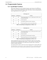
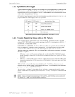
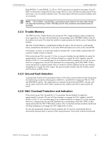
Programming Options Programmable Features 3.2.4 Split Alarm and Silencing DIP switch 8, in conjunction with initiating device signal inputs and DIP switches 1 through 6, is used to program the features of General Alarm, Split Alarm, or Silencing. • DIP switch 8 set to the ON position will split the NAC outputs to pairs. NAC outputs 1 & 2 are controlled by Signal Input 1 and NAC outputs 3 & 4 are controlled by Signal Input 2. The output pairs will be selectively silenced if DIP switches 1 through 6 are set for Pass-through and FACP input is wired and programmed for that operation. • DIP switch 8 set to the OFF position and at least one of the NAC outputs are programmed for synchronization, Signal Input 1 & 2 ON will generate a General Alarm on all four NAC outputs. General Alarm is activation of both visual strobe and audible horns. • DIP switch 8 set to the OFF position and at least one of the NAC outputs are programmed for synchronization, Signal Input 1 ON and Signal Input 1 OFF will silence all four NAC outputs while keeping visual strobe activation. NOTE: See Section 5.1 and 5.2 for proper alarm input wiring when DIP switch 8 is programmed in the OFF position. 38 HPFF12 NAC Expander - P/N 53576:B 11/24/2010
-
 1
1 -
2
-
3
-
4
-
5
-
6
-
7
-
8
-
9
-
10
-
11
-
12
-
13
-
14
-
15
-
16
-
17
-
18
-
19
-
20
-
21
-
22
-
23
-
24
-
25
-
26
-
27
-
28
-
29
-
30
-
31
-
32
-
 33
33 -
 34
34 -
 35
35 -
 36
36 -
 37
37 -
 38
38 -
 39
39 -
 40
40 -
 41
41 -
 42
42 -
 43
43 -
44
-
45
-
46
-
47
-
48
-
49
-
50
-
51
-
52
-
53
-
54
-
55
-
56
-
57
-
58
-
59
-
60
-
61
-
62
-
63
-
64
 |
 |