Honeywell HPFF12 Operation Manual - Page 40
TB2: AC FAIL Contacts, 4.2.3 TB3: Initiating Device Inputs SIGNAL 1 and SIGNAL 2
 |
View all Honeywell HPFF12 manuals
Add to My Manuals
Save this manual to your list of manuals |
Page 40 highlights
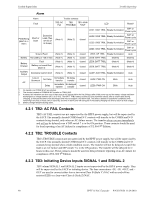
Trouble Supervision Trouble Reporting Alarm Alarm Trouble contacts Fault TB2: AC TB2: TB3: +IN & Fail TROUBLE +OUT LED Reset? LED1: SIG1 TRBL Steady Illumination SW1 or Power cycle Field Wiring (NAC & +/- REF) Short or Open Excessive Load (Two re-tries of >4 Amps) (Note 1) (Note 2) closed LED2: SIG2 TRBL Steady Illumination SW1 or Power cycle LED3: SIG3 TRBL Steady Illumination SW1 or Power cycle LED4: SIG4 TRBL Steady Illumination SW1 or Power cycle Ground Fault (Note 1) (Note 2) closed LED5: GF TRBL Steady Illumination Auto Battery No battery or
-
 1
1 -
2
-
3
-
4
-
5
-
6
-
7
-
8
-
9
-
10
-
11
-
12
-
13
-
14
-
15
-
16
-
17
-
18
-
19
-
20
-
21
-
22
-
23
-
24
-
25
-
26
-
27
-
28
-
29
-
30
-
31
-
32
-
33
-
34
-
 35
35 -
 36
36 -
 37
37 -
 38
38 -
 39
39 -
 40
40 -
 41
41 -
 42
42 -
 43
43 -
 44
44 -
 45
45 -
46
-
47
-
48
-
49
-
50
-
51
-
52
-
53
-
54
-
55
-
56
-
57
-
58
-
59
-
60
-
61
-
62
-
63
-
64
 |
 |
40
HPFF12 NAC Expander —
P/N 53576:B
11/24/2010
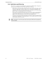
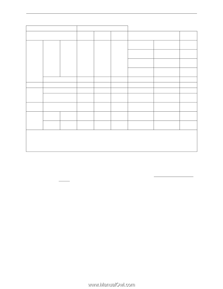
Trouble Supervision
Trouble Reporting
Alarm
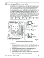
4.2.1
TB2: AC FAIL Contacts
TB2’s AC FAIL contacts are not supervised by the HPFF power supply, but will be supervised by
the FACP. The normally shorted COMM and N/C contacts will transfer to the COMM and N/O
contacts being shorted, only when an AC failure occurs. The transfer
always occurs immediately
and
will not
be delayed even if DIP switch 7 is in the ON position. These contacts should be used
for local reporting of an AC failure for compliance of UL 864 9
th
Edition.
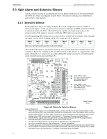
4.2.2
TB2: TROUBLE Contacts
TB2’s TROUBLE contacts are not supervised by the HPFF power supply, but will be supervised by
the FACP. The normally shorted COMM and N/C contacts will transfer to the COMM and N/O
contacts being shorted when a fault condition occurs. The transfer will not be delayed except if the
fault is an AC failure and DIP switch 7 is in the ON position. The transfer will be delayed for 2
hours in this case. These contacts should be used for delayed remote reporting of an AC failure for
compliance of UL 864 9
th
Edition.
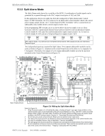
4.2.3
TB3: Initiating Device Inputs SIGNAL 1 and SIGNAL 2
TB3’s alarm SIGNAL 1 and SIGNAL 2 inputs are not supervised by the HPFF power supply. They
will be supervised by the FACP or initiating device. The four connections +IN, –IN, +OUT, and –
OUT are used to connect either from a two-wire/Class B (Style Y) NAC with an end-of-line
resistor (ELR) or a four-wire/Class A (Style Z) NAC.
Alarm
Trouble contacts
Fault
TB2: AC
Fail
TB2:
TROUBLE
TB3: +IN &
+OUT
LED
Reset?
Field Wiring
(NAC & +/-
REF)
Short or
Open
Excessive
Load (Two
re-tries of
>4 Amps)
(Note 1)
(Note 2)
closed
LED1: SIG1 TRBL
Steady Illumination
SW1 or
Power cycle
LED2: SIG2 TRBL
Steady Illumination
SW1 or
Power cycle
LED3: SIG3 TRBL
Steady Illumination
SW1 or
Power cycle
LED4: SIG4 TRBL
Steady Illumination
SW1 or
Power cycle
Ground Fault
(Note 1)
(Note 2)
closed
LED5: GF TRBL
Steady Illumination
Auto
Battery
No battery or <20.5 VDC
(Note 1)
(Note 1)
closed
LED6: BATT TRBL
(Note 4)
(Note 4)
Battery
Charger
Fault
(Note 1)
(Note 1)
closed
LED6: BATT TRBL
(Note 4)
(Note 4)
Battery not reach float
(Note 3)
(Note 1)
(Note 1)
closed
LED6: BATT TRBL
(Note 4)
(Note 4)
Auxiliary
Output
Excessive load or short
(Note 1)
(Note 1)
closed
LED7: AUX TRBL
Steady Illumination
Auto
AC
Loss or
Brownout
No Delay
Immediate
transfer
No delay
transfer
closed
LED8: PWR ON
Blink
Auto
Delay
Immediate
transfer
2hr delayed
transfer
closed
LED8: PWR ON
Blink
Auto
1.
No transfer and COMM & N/C are shorted.
2.
The shorted contacts of COMM & N/C transfer to COM & N/O.
3.
A battery fail indication can also occur if there was an AC failure within the first 24 hours after initial power-up and the battery voltage had been
discharged to a voltage between 20.5- 26.5 VDC. The BATT TRBL battery trouble LED may illuminate steady, after a certain delay during
charging, to indicate the battery was discharged and may not support a full alarm load. The delay is based on operational conditions (time
remaining in the first 24 hours, time in stand-by, and time in alarm) and will extinguish if the battery charging has time to reach its float voltage.
4.
Battery Charger disabled during alarm.