Honeywell HPFF12 Operation Manual - Page 41
Trouble Memory, 4.2.5 Ground Fault Detection, 4.2.6 NAC Overload Protection and Indication
 |
View all Honeywell HPFF12 manuals
Add to My Manuals
Save this manual to your list of manuals |
Page 41 highlights
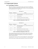
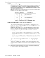
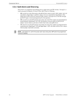
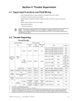
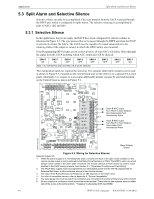
Trouble Reporting Trouble Supervision Both SIGNAL 1's and SIGNAL 2's +IN to +OUT connections are opened to disconnect Class B ELR's or the positive connection of Class A input. However, they will always remain closed* in the alarm state, even if a trouble condition exists. The alarm signal will then be passed if multiple units are connected. NOTE: *TB3's SIGNAL 1 and SIGNAL 2 connections remain closed in the alarm state. Always use supervised monitoring of TB2's TROUBLE and AC FAIL contacts to annunciate troubles at the FACP. 4.2.4 Trouble Memory The HPFF has NAC Trouble Memory by storing the NAC output number(s) when a trouble has been experienced. The unit will then blink the corresponding yellow SIGTRBL LED(s) when all the troubles are cleared. This helps the installer or repair personnel to find the cause of intermittent troubles. The NAC Trouble Memory is permanently latched. To clear it, the AC must be cycled and the battery momentarily disconnected, or just press SW2 (microprocessor reset) on the control PCB. If the panel is in alarm, an excessively loaded or shorted NAC is only trouble condition that will cause the Trouble contacts to transfer. If the current in any NAC exceeds 3.5 A due to excessive loading, the unit disables its output for approximately 8 seconds. The unit will then attempt to re-engage the NAC output(s), and will disable it if the 3.5 A is exceeded again. If an overload condition exceeding 4.0 A exists for more than two re-engagements, the unit will illuminate the corresponding yellow SIG TRBL LED(s) steady and generate a general trouble. This is a latched overload condition, but the unit will keep attempting to re-engage the NAC output. The general trouble transfers only the Trouble contact until the alarm condition clears. 4.2.5 Ground Fault Detection A ground fault trouble will be generated if there is 50 K ohms or lower between Earth Ground and the field wiring, except the initiating device SIGNAL 1 and SIGNAL2 inputs and TB2 AC FAIL and TROUBLE contacts. The signal inputs are optically-isolated from the HPFF's circuitry and will be supervised by the FACP. TB2's contacts are dry contacts and will be supervised by the FACP. 4.2.6 NAC Overload Protection and Indication If the current in any NAC exceeds the 3.5 A maximum, the unit disables its output for approximately 8 seconds. The unit will then attempt to re-engage the NAC output(s), and will disable it if the 3.5 A is exceeded again. If an overload condition exceeding 4.0 A exists for more than two re-engagements, the unit will illuminate the corresponding yellow SIG TRBL LED(s) steady and transfer the TB2's TROUBLE contacts. This is a latched overload condition, but the unit will keep attempting to re-engage the NAC output while in alarm. To clear the permanently latched overload condition, the AC must be cycled and the battery momentarily disconnected, or just press SW2 (microprocessor reset) on the Control circuit board. HPFF12 NAC Expander - P/N 53576:B 11/24/2010 41
-
 1
1 -
2
-
3
-
4
-
5
-
6
-
7
-
8
-
9
-
10
-
11
-
12
-
13
-
14
-
15
-
16
-
17
-
18
-
19
-
20
-
21
-
22
-
23
-
24
-
25
-
26
-
27
-
28
-
29
-
30
-
31
-
32
-
33
-
34
-
35
-
 36
36 -
 37
37 -
 38
38 -
 39
39 -
 40
40 -
 41
41 -
 42
42 -
 43
43 -
 44
44 -
 45
45 -
 46
46 -
47
-
48
-
49
-
50
-
51
-
52
-
53
-
54
-
55
-
56
-
57
-
58
-
59
-
60
-
61
-
62
-
63
-
64
 |
 |