Honeywell HPFF12 Operation Manual - Page 44
Split Alarm and Selective Silence, 5.3.1 Selective Silence
 |
View all Honeywell HPFF12 manuals
Add to My Manuals
Save this manual to your list of manuals |
Page 44 highlights
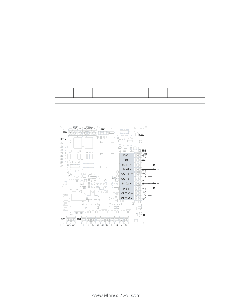
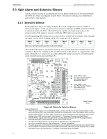
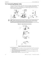
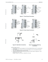
Applications Split Alarm and Selective Silence 5.3 Split Alarm and Selective Silence Selective silence can only be accomplished if the sync protocol from the FACP is passed through the HPFF unit, which is configured for Split Alarm. The selective silencing is accomplished in pairs of NACs 1&2 and 3&4. 5.3.1 Selective Silence In this application, the power supply and FACP have been configured for selective silence as illustrated in Figure 5.3. The sync protocol has to be passed through the HPFF unit from the FACP to selectively silence the NACs. The FACP must be capable of a visual annunciation to the silencing status of the output or zone(s) to which the HPFF unit(s) are connected. If the Programming DIP Switches are set as shown below, all four NACs will follow (Pass-through) the signal from the FACP including which NAC output pair will be silenced. SW1-8 ON SW1-7 NA SW1-6 OFF SW1-5 OFF SW1-4 OFF NAC 1 & 2 will NOT be silenced; NAC 3 & 4 will be silenced. SW1-3 OFF SW1-2 OFF SW1-1 ON Two independent inputs are required for silencing. Two separate addressable modules can be used as shown in Figure 5.2, mounted on the control board (one on the other) or in a separate UL-Listed panel. Alternately, two outputs of a six-output addressable module can also be used and mounted on the Control board as shown in Figure 5.4. Class B NAC output from FACP or Sync Module: Non-Silenceable Point Activated by Alarm Class B NAC output from FACP or Sync Module: Silenceable Point Activated by Alarm HPFF8-selsil.wmf Alarm Polarity Shown Figure 5.3 Wiring for Selective Silence Notes for Figure 5.3: 1. When the power supply is in normal/standby state, a trouble will result in an open circuit condition on the control module output circuit (monitored by the End-of-Line Resistors on TB3). The HPFF's alarm circuit will always remain closed in the alarm state. Therefore, the Trouble contacts at TB2 need to be used to report troubles to the FACP during an alarm. See Section 4.1, "Supervised Functions and Field Wiring". 2. The FACP NAC outputs must be programmed as a silenceable points and the HPFF8 programmed for Selective/Split Alarm to allow selective silence of horn/strobe devices. 3. The value of the ELRs (End-of-Line Resistors) on TB3 depends on the FACP used. 4. For a list of compatible devices, refer to Appendix A, "Device Compatibility". 5. The same gauge wire must be used if two conductors are connected to the same terminal of any terminal block. 6. Do not complete a continuous circuit around the screw terminal. There must be two separate wires on either side of the screw at the terminal block. "T-tapping" is absolutely NOT ALLOWED. 44 HPFF12 NAC Expander - P/N 53576:B 11/24/2010
-
 1
1 -
2
-
3
-
4
-
5
-
6
-
7
-
8
-
9
-
10
-
11
-
12
-
13
-
14
-
15
-
16
-
17
-
18
-
19
-
20
-
21
-
22
-
23
-
24
-
25
-
26
-
27
-
28
-
29
-
30
-
31
-
32
-
33
-
34
-
35
-
36
-
37
-
38
-
 39
39 -
 40
40 -
 41
41 -
 42
42 -
 43
43 -
 44
44 -
 45
45 -
 46
46 -
 47
47 -
 48
48 -
 49
49 -
50
-
51
-
52
-
53
-
54
-
55
-
56
-
57
-
58
-
59
-
60
-
61
-
62
-
63
-
64
 |
 |