Honeywell HPFF12 Operation Manual - Page 46
Connecting Multiple Units, Typical System Connections, System Sync Connections
 |
View all Honeywell HPFF12 manuals
Add to My Manuals
Save this manual to your list of manuals |
Page 46 highlights
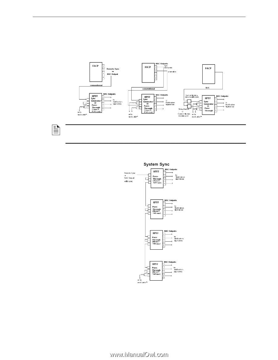
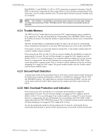
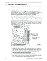
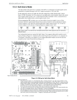
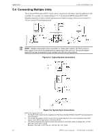
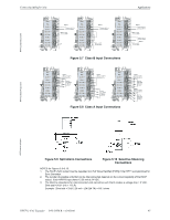
Applications Connecting Multiple Units 5.4 Connecting Multiple Units Two or more HPFF8 and/or HPFF12 units can be connected to each other to provide additional NAC extenders for a system; see wiring in Figures 5.5-5.10 and in the HPFF8 manual PN 53499. Maintain separation of power-limited and non-power limited wiring as discussed in Section 2.5, "Power-Limited Wiring Requirements". HPFFconnex-typ.psd NOTE: Multiple units should not be connected in a "daisy chain" fashion. DO NOT connect a NAC output of one unit to the initiating device signal input of the next unit. The synchronization signal will not pass unimpeded through multiple units with this wiring method. Figure 5.5 Typical System Connections HPFFconnex-SysSync.psd Figure 5.6 System Sync Connections NOTES for Figures 5.5-5.10: 1. The FACP's NAC output must be regulated (not Full Wave Rectified [FWR]) if the HPFF is programmed for Sync Generator. 2. The number of possible units that can be interconnected depends on the current capability of the FACP output. Each HPFF8 input draws 12.26 mA at 24 VDC. 3. The total line impedance for interconnected units cannot be such that it creates a voltage drop > 2 VDC. Zline total =2V/(1 Unit + 1 ELR) Example: Zline total = 2V/(12.26 mA + (24-2)/4.7K) =118.1 ohms 46 HPFF12 NAC Expander - P/N 53576:B 11/24/2010
-
 1
1 -
2
-
3
-
4
-
5
-
6
-
7
-
8
-
9
-
10
-
11
-
12
-
13
-
14
-
15
-
16
-
17
-
18
-
19
-
20
-
21
-
22
-
23
-
24
-
25
-
26
-
27
-
28
-
29
-
30
-
31
-
32
-
33
-
34
-
35
-
36
-
37
-
38
-
39
-
40
-
 41
41 -
 42
42 -
 43
43 -
 44
44 -
 45
45 -
 46
46 -
 47
47 -
 48
48 -
 49
49 -
 50
50 -
 51
51 -
52
-
53
-
54
-
55
-
56
-
57
-
58
-
59
-
60
-
61
-
62
-
63
-
64
 |
 |