Honeywell HPFF12 Operation Manual - Page 50
How to Calculate System Current Draw, Table 6.4, System Current Draw Calculations
 |
View all Honeywell HPFF12 manuals
Add to My Manuals
Save this manual to your list of manuals |
Page 50 highlights
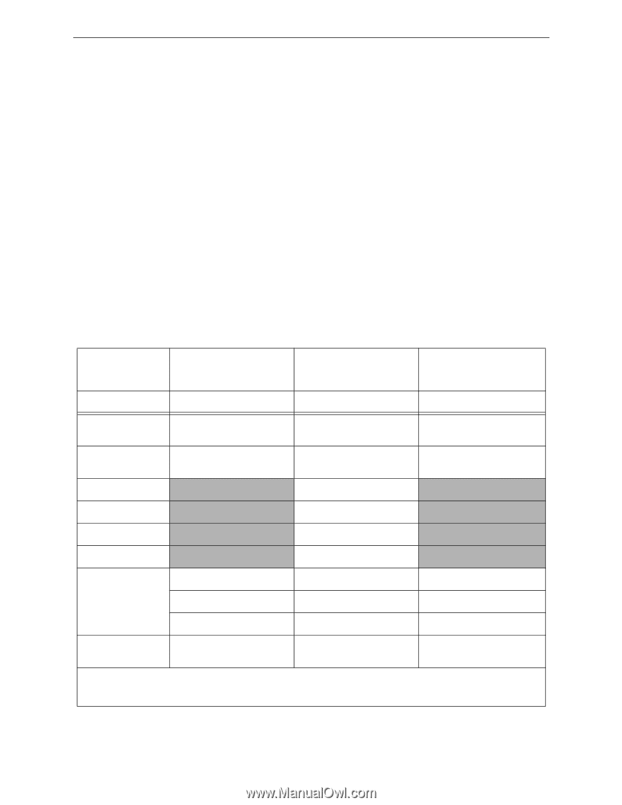
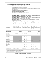
Power Supply Requirements Calculating the System Current Draw 6.3.2 How to Calculate System Current Draw Use Table 6.4 to calculate current draw as follows: 1. Enter the quantity of devices in all three columns. 2. Enter the current draw where required. Refer to the specifications of compatible devices for their current draw. 3. Calculate the current draws for each in all columns. 4. Sum the total current for each column. 5. Copy the totals from Column 2 and Column 3 to Table 6.4. Following are the types of current that can be entered into Table 6.4 on page 50. • Calculation Column 1 - The primary AC supply current load that the power supply must support during a non-alarm condition, with AC power applied • Calculation Column 2 - The primary AC supply current load that the power supply must support during an alarm condition, with AC power applied • Calculation Column 3 - The standby current drawn from the batteries in a non-alarm condition during a loss of AC Table 6.4 contains three columns for calculating current draws. For each column, calculate and enter the total (in amperes) in the bottom row. When finished, copy the totals from Calculation Column 2 and Calculation Column 3 to Table 6.5. Device Type Main Circuit Board Calculate Column 1 Primary, Non-Alarm Current (Amps RMS) Calculate Column 2 Primary, Fire Alarm Current (DC Amps) Calculate Column 3 Secondary, Non-Alarm Current (DC Amps) Qty X (current draw) = Total Qty X (current draw) = Total Qty Excrement draw) = Total =[0.207] =[0.206] = [0.075] Trouble Contacts (coil current) NAC Output #11 1 X [0.0659] = 1 X [0.0659] = [ ] X[ ] = = 0.0 NAC Output #2 [ ] X[ ] = NAC Output #3 [ ] X[ ] = NAC Output #4 [ ] X[ ] = Auxiliary Output Current Draw from TB42 Terminals +A & -A [ ] X[ ] = [ ] X[ ] = [ ] X[ ] = Sum each column for total: Primary Non-Alarm = Primary Alarm3= Secondary Non-Alarm = 1. Current limitation on TB4 NAC circuits is 3.0 Amps per NAC. 2. Current limitation on TB4 AUX Output is 2.0 Amps. 3. Total current draw cannot exceed 12.0 Amps in alarm. Table 6.4 System Current Draw Calculations 50 HPFF12 NAC Expander - P/N 53576:B 11/24/2010
-
 1
1 -
2
-
3
-
4
-
5
-
6
-
7
-
8
-
9
-
10
-
11
-
12
-
13
-
14
-
15
-
16
-
17
-
18
-
19
-
20
-
21
-
22
-
23
-
24
-
25
-
26
-
27
-
28
-
29
-
30
-
31
-
32
-
33
-
34
-
35
-
36
-
37
-
38
-
39
-
40
-
41
-
42
-
43
-
44
-
 45
45 -
 46
46 -
 47
47 -
 48
48 -
 49
49 -
 50
50 -
 51
51 -
 52
52 -
 53
53 -
 54
54 -
 55
55 -
56
-
57
-
58
-
59
-
60
-
61
-
62
-
63
-
64
 |
 |