Honeywell HPFF12 Operation Manual - Page 59
Index
 |
View all Honeywell HPFF12 manuals
Add to My Manuals
Save this manual to your list of manuals |
Page 59 highlights
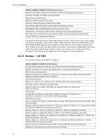
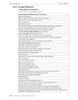
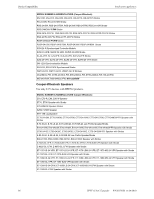
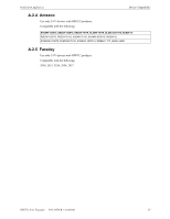
I ndex A AC branch circuit 48 AC FAIL 9, 11, 14, 15, 35, 37, 39, 40, 41 AC Fail Contact Rating 14 AC loss 9, 11, 14, 37, 39, 40, 48 AC Power Wiring 13, 32, 33, 34 addressable control or relay modules 30-31 Alarm load calculations 51 Applications Connecting multiple units 46 controlling and silencing 4 NACs 43 Four NAC circuits controlled by a single source 42 Selective silence 44 Split alarm mode 45 Auxiliary Output TB4 on Control circuit board 15 B backbox 17 dimensions 18, 19, 20 Batteries selection and placement 51 battery using one battery with multiple HPFFs 12 Battery Charging Circuit (TB1 on Control circuit board) 14 brownout 13 brownout (see AC loss) C cabinet 17, 21 dimensions 18, 19, 20 Calculating AC branch circuit current 48 Battery Size 51 Power supply currents 48 System Current Draw 49, 50 Calculating fire alarm load 49 Calculating power supply requirements procedures 48 Charger Disable Jumper (J1) 12 chassis removing 17 Chassis-mounting 21 Class A (Style Z) 27 Class A (Style Z) Adaptor 29 Class B (Style Y) 26, 28 clearing the permanently latched overload condition 41 conduit knockouts 31 Contact ratings 14 Control and relay modules 53 Control Panel Circuit Board 15 Converting milliamperes and microamperes to full amperes 49 Current Draw Calculations 49 D Delay 35 Delayed trouble reporting 37 Device Compatibility Listing Amseco 57 Cooper Wheelock 55, 56 Faraday 57 Gentex 54 System Sensor 53 Device compatibility listings 53-57 dimensions cabinet 18, 19, 20 DIP switch settings 35 Selective silence 44 Split alarm and silencing 38 Split alarm mode 45 Synchronization 37 E EQBB-D4 see cabinet excessive loading 41 F Features 10 Field-Programming 35 filtered feature 36 Fire Alarm Control Panel cabinet, see Large Equipment Enclosure Form-C relay contacts (also see TROUBLE and AC FAIL) 11 G Ground Fault Detection 41 Ground Fault Disable Jumper (J2) 12 ground monitoring 12 H HPFF12CM installation 21 HPP31076 29 I Initiating Device Signal Inputs (TB3 on Control HPFF12 NAC Expander - P/N 53576:B 11/24/2010 59
-
 1
1 -
2
-
3
-
4
-
5
-
6
-
7
-
8
-
9
-
10
-
11
-
12
-
13
-
14
-
15
-
16
-
17
-
18
-
19
-
20
-
21
-
22
-
23
-
24
-
25
-
26
-
27
-
28
-
29
-
30
-
31
-
32
-
33
-
34
-
35
-
36
-
37
-
38
-
39
-
40
-
41
-
42
-
43
-
44
-
45
-
46
-
47
-
48
-
49
-
50
-
51
-
52
-
53
-
 54
54 -
 55
55 -
 56
56 -
 57
57 -
 58
58 -
 59
59 -
 60
60 -
 61
61 -
 62
62 -
 63
63 -
 64
64
 |
 |