Honeywell NSEK Configuration Guide
Honeywell NSEK Manual
 |
View all Honeywell NSEK manuals
Add to My Manuals
Save this manual to your list of manuals |
Honeywell NSEK manual content summary:
- Honeywell NSEK | Configuration Guide - Page 1
NS2 Configuration Guide Contents Description 1 Specifications 1 Power 1 Backup Battery 1 Secondary Backup Battery a maximum current of 600 mA. Five volt (5 VDC) readers require five-volt regulators (Northern part no. 5VRDREG) Maximum draw is less then 600 mA: (Reader 1+ Reader 2 + Aux Power - Honeywell NSEK | Configuration Guide - Page 2
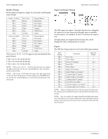
NS2 Configuration Guide Honeywell Access Systems Reader Wiring Each reader port supports a single 12-volt Reader LED Control Data 0 Signal Data 1 Signal Common 12VDC Power Tamper NS2 version 1.01.01 - 1.03.09 supports only the defaulted Wiegand formats: F=PN 1 26 S 1 D 1 B1 B2 B3 B4 F=PN 2 32 S - Honeywell NSEK | Configuration Guide - Page 3
Honeywell Access Systems NS2 Configuration Guide Outputs Four form-C relays SPDT (Single Poll Double Throw) the normal operation of other equipment. To minimize premature contact failure and increase system reliability, contact circuit protection such as the S-4 suppressor is required. Locate this - Honeywell NSEK | Configuration Guide - Page 4
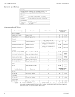
NS2 Configuration Guide Honeywell Access Systems Enclosure Specifications Mounting One NS2 panel in a standard 19-inch, high density enclosure. Up to modem), F210D (Fiber to RS-232) [Discontinued] and F290D (Fiber to RS-485) [Discontinued] are not supported with the NS2 panel(s). 4 7-101004-01 - Honeywell NSEK | Configuration Guide - Page 5
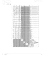
Honeywell Access Systems DIP Switch Settings NS2 Configuration Guide S1 S2 S3 S4 S5 S6 S7 S8 S9 S10 SELECTION OFF OFF OFF OFF OFF Address 0 ON OFF OFF OFF OFF Address 1(default) OFF - Honeywell NSEK | Configuration Guide - Page 6
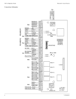
NS2 Configuration Guide Connection Schematic Honeywell Access Systems TB1 READER2 READER1 PWR FAIL/ - TB9 RS485 COM PWR ON LED AC/DC + PWR ON LED AC/DC - C1 PF C2 RUN SYSTEM STATUS LEDS 1 ON DIPSWITCHES OPTIONAL ETHERNET INTERFACE 10 RELAY LEDS 3 1 4 2 RELAY1 RELAY2 X PORT RELAY3 - Honeywell NSEK | Configuration Guide - Page 7
Honeywell Access Systems Configuration Diagrams RS-232 Connection One NS2 panel for each COM port. NS2 Configuration Guide NStar Server COM 1 COM 2 CBL50 (RS-232) 50 ft. Max. CBL50 (RS-232) 50 ft. Max. NS2 Panel DIP Switch Settings S1-S5: Panel Address - Honeywell NSEK | Configuration Guide - Page 8
NS2 Configuration Guide RS-485 Connection Thirty-one NS2 panels for each drop line. Honeywell Access Systems NStar Server COM Port RS- 4,000 ft. (1,200 m) max, 24 AWG, 2 twisted pairs with shield, 120 ohm, 23 pf (NCI part no. NCP2441-TN) DIP Switch Settings S1: ON S2: ON S3: ON S4: ON S5: ON S6: - Honeywell NSEK | Configuration Guide - Page 9
Honeywell Access Systems NSLAN1 Connection One NSLAN1 for each NS2 panel, Maximum sixty-four IP connections. NS2 Configuration Guide NIC 100BaseT ( with a static IP address See NSLAN1 product documentation for programing instructions. NS2 Panel NSLAN1 installed 100BaseT (CAT 5) 328 Ft. Max - Honeywell NSEK | Configuration Guide - Page 10
Guide LANSRL100 Connection Thirty-one NS2 panels for each drop line, Maximum sixty-four IP connections. Honeywell Access Systems NIC (1,200 m) max, 24 AWG, 2 twisted pairs with shield, 120 ohm, 23 pf (NCI part no. NCP2441-TN) 100BaseT (CAT 5) 328 Ft. Max. LANSRL100 DIP Switch Settings S1: ON - Honeywell NSEK | Configuration Guide - Page 11
Honeywell Access Systems LANSRLU1 Connection Thirty-one panels for each drop line, Maximum sixty-four IP connections. NS2 Configuration Guide NIC (1,200 m) max, 24 AWG, 2 twisted pairs with shield, 120 ohm, 23 pf (NCI part no. NCP2441-TN) LANSRLU1 DIP Switch Settings S1: ON S2: ON S3: ON S4: ON - Honeywell NSEK | Configuration Guide - Page 12
NS2 Configuration Guide Lease Line Modem Connection Thirty-one (TX) 3 (RX) 7 (Comm) RS-232 (50 Ft.) M-9600-LA RS-485 (4,000 Ft.) Honeywell Access Systems Lease Line Phone Line DIP Switch Settings S1: ON S2: ON S3: ON S4: ON S5: ON S6 , 120 ohm, 23 pf (NCI part no. NCP2441-TN) 12 7-101004-01 - Honeywell NSEK | Configuration Guide - Page 13
Honeywell Access Systems RS-485 Short Haul Modem Connection Thirty- ) 4,000 ft. (1,200 m) max, 24 AWG, 2 twisted pairs with shield, 120 ohm, 23 pf (NCI part no. NCP2441-TN) NS2 Configuration Guide SHM-B-ASYNC Short Haul Modem RS232 Cable PC (DB-9) 2 TX 3 RX 5 Comm MODEM DTE (Straight) DCE ( - Honeywell NSEK | Configuration Guide - Page 14
NS2 Configuration Guide RS-232 Short Haul Modem Connection One NS2 panel for each loop. NStar Server RS-232, 50 Ft. Max. SHM-B-ASYNC Short Haul Modem Honeywell Access Systems RS232 Cable PC (DB-9) 2 TX 3 RX 5 Comm MODEM DTE (Straight) DCE (Null) 2 (TX) 3 (RX) or 7 (GND) 2 (RX) 3 (TX) 7 (GND - Honeywell NSEK | Configuration Guide - Page 15
Honeywell Access Systems M-9600 Dial-up Modem, RS-485 Connection Thirty-one NS2 panels for each drop line. NS2 Configuration Guide NStar Server Refer to 485-PCI / NS2 Panel Connection Detail diagram. N-485-HUB-2 , 24 AWG, 2 twisted pairs with shield, 120 ohm, 23 pf (NCI part no. NCP2441-TN) 15 - Honeywell NSEK | Configuration Guide - Page 16
NS2 Configuration Guide M-56K Dial-up Modem, RS-485 Connection Thirty-one NS2 panels for each drop line. Honeywell Access Systems NStar Server Refer to 485-PCI/ NS2 Panel Connection Detail diagram. N- 24 AWG, 2 twisted pairs with shield, 120 ohm, 23 pf (NCI part no. NCP2441-TN) 16 7-101004-01 - Honeywell NSEK | Configuration Guide - Page 17
Honeywell Access Systems Fiber Converter to RS-485 Connection Thirty-one NS2 panels for each drop line. NS2 Configuration Guide COM Port Refer to 485-PCI/NS2 Panel Connection Detail diagram. RS m) max, 24 AWG, 2 twisted pairs with shield, 120 ohm, 23 pf (NCI part no. NCP2441-TN) 7-101004-01 17 - Honeywell NSEK | Configuration Guide - Page 18
Guide 485-PCI/NS2 Panel Connection Detail DIP Switch Settings S1: ON S2: ON S3: ON S4: ON S5: ON S6: OFF (Ack/Nak on) S7: ON S8: OFF (19,200 Baud Rate) To Serial Connection See 485 Interface connection note. Honeywell Access Systems (NCI part no. NCP2441-TN). GREEN BLACK RED WHITE 18 7-101004-01 - Honeywell NSEK | Configuration Guide - Page 19
available? Honeywell Access has made the NS2 available in pre-packaged kits to make ordering easier. Part No. NSSKR NSSK NSEKR NSEK Kit Description ) Does the NStar software or hardware support USB ports for communications? Please contact Honeywell Access Systems for further details. What is the - Honeywell NSEK | Configuration Guide - Page 20
Honeywell Access Systems NS2 Configuration Guide Question: Can the NS2 panel run in a LAN/WAN using the 485-PCI-2L and a LANSRL100 or NLANSRLU1 (64 max). Question: Does the NS2 panel support Anti-Passback? Yes. Question: What is the Xport expansion port used for? The XPort expansion port
-
 1
1 -
 2
2 -
 3
3 -
 4
4 -
 5
5 -
 6
6 -
 7
7 -
8
-
9
-
10
-
11
-
12
-
13
-
14
-
15
-
16
-
17
-
18
-
19
-
20
 |
 |

7-101004-01
1
NS2 Configuration Guide
Contents
Description . . . . . . . . . . . . . . . . . . . . . . . . . . . . . . . . . . . . . . . 1
Specifications . . . . . . . . . . . . . . . . . . . . . . . . . . . . . . . . . . . . . 1
Power . . . . . . . . . . . . . . . . . . . . . . . . . . . . . . . . . . . . . . . . 1
Backup Battery. . . . . . . . . . . . . . . . . . . . . . . . . . . . . . . . . 1
Secondary Backup Battery. . . . . . . . . . . . . . . . . . . . . . . . 1
Reader & Aux Power . . . . . . . . . . . . . . . . . . . . . . . . . . . . 1
Reader Wiring . . . . . . . . . . . . . . . . . . . . . . . . . . . . . . . . . 2
Supervised Input Wiring . . . . . . . . . . . . . . . . . . . . . . . . . 2
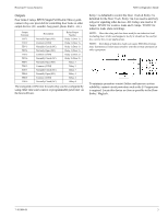
Inputs . . . . . . . . . . . . . . . . . . . . . . . . . . . . . . . . . . . . . . . . 2
Outputs . . . . . . . . . . . . . . . . . . . . . . . . . . . . . . . . . . . . . . . 3
Enclosure Specifications . . . . . . . . . . . . . . . . . . . . . . . . . 4
Communications & Wiring . . . . . . . . . . . . . . . . . . . . . . . 4
DIP Switch Settings . . . . . . . . . . . . . . . . . . . . . . . . . . . . . 5
Connection Schematic . . . . . . . . . . . . . . . . . . . . . . . . . . . 6
Configuration Diagrams . . . . . . . . . . . . . . . . . . . . . . . . . . . . . 7
RS-232 Connection . . . . . . . . . . . . . . . . . . . . . . . . . . . . . 7
RS-485 Connection . . . . . . . . . . . . . . . . . . . . . . . . . . . . . 8
NSLAN1 Connection. . . . . . . . . . . . . . . . . . . . . . . . . . . . 9
LANSRL100 Connection. . . . . . . . . . . . . . . . . . . . . . . . 10
LANSRLU1 Connection . . . . . . . . . . . . . . . . . . . . . . . . 11
Lease Line Modem Connection . . . . . . . . . . . . . . . . . . . 12
RS-485 Short Haul Modem Connection . . . . . . . . . . . . 13
RS-232 Short Haul Modem Connection . . . . . . . . . . . . 14
M-9600 Dial-up Modem, RS-485 Connection . . . . . . . 15
M-56K Dial-up Modem, RS-485 Connection . . . . . . . . 16
Fiber Converter to RS-485 Connection . . . . . . . . . . . . . 17
485-PCI/NS2 Panel Connection Detail . . . . . . . . . . . . . 18
Frequently Asked Questions
. . . . . . . . . . . . . . . . . . . . . . . . . . . . 19
Description
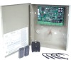
The NS2 is a two reader panel providing access control for up
to two doors through the use of Wiegand readers.
The NS2 may be used as a standalone panel with independent
card and transaction storage or, with a software upgrade, as a
fully monitored online access control device. Communication
to the front-end computer is achieved through an RS-232 serial
cable (included with installation kit) or an optional RS-485
interface. Each RS-485 interface is capable of communicating
with up to 31 panels.
The NS2 is designed for tile mount using the ENC10 enclo-
sure. The I/O terminals are organized by operational utility
with connectors for power and RS-485 communications
located on the lower right followed from right to left by the
relays, auxiliary power, door control inputs, and readers. The
Tamper and External Power Fail terminal are located at the left
edge above the main line of connectors.
Specifications
Power
AC Non-Polarized:
16.5 VAC utilizing a UL-listed 50 VA Class 2 transformer
(TB9-4 AC+/TB9-5 AC–)
or
DC Polarized:
24 VDC, 1.25 Amp (TB9-4 DC+/TB9-5 DC–)
Power Wire
Two-wire, 18 AWG, shielded cable.
Backup Battery
Casil 12 VDC (NCI Part #: BAT-3) 4Ah, sealed acid/lead
backup battery (J6 DC+/J7 DC–)
Backup battery will provide 2.5 hours of standby backup
power.
Charging voltage: 13.7 +/– 0.1 VDC
NOTE:
The NS2 panel has deep discharge protection built in for the
protection of the battery and will only utilize a backup battery down to
10.2 VDC before the NS2 shuts down. Backup battery should be
replaced 2 to 2.5 years: more often if panel has a high rate of backup
use.
Secondary Backup Battery
The NS2 panel memory is backed up using a super capacitor
for one week in the absence of power or a backup battery. The
super capacitor will backup panel memory and real-time clock
and does not require maintenance or replacement.
Reader & Aux Power
Reader and AUX power is supplied at 10.8-12.7 VDC with a
maximum current of 600 mA.
Five volt (5 VDC) readers require five-volt regulators (North-
ern part no. 5VRDREG)
Maximum draw is less then 600 mA: (Reader 1+ Reader 2 +
Aux Power) < 600 mA.
NOTE:
Aux power must not be used to power locks.