Honeywell RTH2520B Owner's Manual
Honeywell RTH2520B Manual
 |
View all Honeywell RTH2520B manuals
Add to My Manuals
Save this manual to your list of manuals |
Honeywell RTH2520B manual content summary:
- Honeywell RTH2520B | Owner's Manual - Page 1
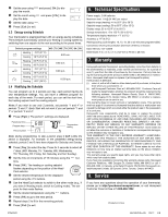
on (continuous) • Programmable heating and cooling cycle lengths: 10, 12, 15, 20 or 30 minutes • Temperature display in °F or °C • Backlit display • Battery replacement indicator • 7-day programming including: - Preprogrammed energy-saving schedule - Early Start - Temporary bypass - Time display (12 - Honeywell RTH2520B | Owner's Manual - Page 2
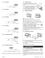
the wall, the thermostat will display the ambient temperature. By default, the setpoint is 70°F (21°C). The time and day settings flash to indicate that they must be set (see section 5.1). 2.6 Completing the Installation Jumper Heat relay Cool relay Fan relay 2.3.6 5-wire Heating and Cooling Fan - Honeywell RTH2520B | Owner's Manual - Page 3
. After replacing the batteries, set the time, day and date (see sections 5.1 and 5.2). However, the temperature and program settings are saved and do not need to be re-entered. Warning: Before removing the batteries, place the system switch on the thermostat to Off. Otherwise, the heating/cooling - Honeywell RTH2520B | Owner's Manual - Page 4
(0.5°C) Heating/cooling cycle lengths: 10, 12, 15, 20 or 30 minutes (programmable) Compressor short-cycle protection (minimum off time): 5 minutes Data memory: non-volatile Dimensions: 5 in. x 3 in. x 1 in. (127 mm x 75 mm x 28 mm) 7. Warranty Honeywell warrants this product, excluding battery, to - Honeywell RTH2520B | Owner's Manual - Page 5
Instalación y guía para el usuario 1. Introducción El termostato programable RTH2520 puede usarse para controlar: • Un sistema de calefacción que de funcionamiento del ventilador: automático o encendido (continuo) • Duración programable de los ciclos de calefacción y enfriamiento: 10, 12, 15, 20 - Honeywell RTH2520B | Owner's Manual - Page 6
Puente JP2 Retire cuidadosamente la tapa de las baterías. Instale las baterías como se indica en la figura. Preste atención rojo ubicado entre las terminales Rc y Rh. RTH2520 Una vez que la placa de la base en el modo de calefacción (HEAT) o en el modo de enfriamiento (COOL), o para - Honeywell RTH2520B | Owner's Manual - Page 7
manual o de retención permanente Mantiene la temperatura en un valor fijo establecido. Para poner el termostato en este modo, pulse [ Mode ]. Desaparecerá el icono de la casa. 3.6.2 Modo programable baterías Cuando el icono comience a parpadear, instale baterías nuevas. El icono comienza a titilar - Honeywell RTH2520B | Owner's Manual - Page 8
): 10, 12, 15, 20 ó 30 minutos (programable) Protección de ciclos cortos del compresor (tiempo mínimo de apagado): 5 minutos Memoria de datos: no volátil Dimensiones: 5 x 3 x 1 pulgadas (127 mm x 75 mm x 28 mm) 7. Garantía Honeywell garantiza por un período de un (1) año, a partir de la fecha
-
 1
1 -
 2
2 -
 3
3 -
 4
4 -
 5
5 -
 6
6 -
 7
7 -
8
 |
 |
RTH2520
69-1867ES—05
03-11
1/8
The RTH2520 programmable thermostat can be used to control:
•
a gas, fuel oil or electric furnace -2 or 3 wires
•
a central air conditioner - 2 or 3 wires
•
a hot water system with or without pump - 2 wires
•
a millivolt system - 2 wires
•
a central heating and cooling system - 4 or 5 wires
Note
: This thermostat is not compatible with heat pumps or multi-
stage systems.
Features
•
System operating mode selection: heat, cool or off
•
Fan operating mode selection: automatic or on (continuous)
•
Programmable heating and cooling cycle lengths: 10, 12, 15, 20
or 30 minutes
•
Temperature display in °F or °C
•
Backlit display
•
Battery replacement indicator
•
7-day programming including:
- Preprogrammed energy-saving schedule
- Early Start
- Temporary bypass
- Time display (12 h or 24 h)
•
Filter replacement indicator
•
Automatic daylight savings changeover
•
Interchangeable faceplates (titanium, charcoal & taupe)
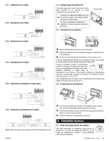
2.1
Removing the Old Thermostat
IN ORDER TO AVOID ANY RISK OF ELECTRIC SHOCK, CUT
POWER TO THE HEATING/COOLING SYSTEM.
Remove the old thermostat to access the wires.
Warning
: If the old thermostat was mounted onto an electrical box,
it was probably powered by 120/240 volts. In this case, this thermo-
stat cannot be used.
Identify and label each wire (with the corresponding letter on
the wire terminal) and remove them from the terminals.
If necessary, strip the end of each wire (maximum of 1/4 inch).
Wrap the wires around a pencil to prevent
them from falling into the wall.
If the hole in the wall is too big, insulate it
using a non-flammable material in order to
avoid air draughts behind the thermostat.
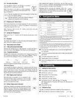
2.2
Installing the New Baseplate
For a new installation, choose a location approximately 5 feet
(1.5 m) above the floor and on an inside wall. Avoid draughty
areas (top of staircase, air outlet, etc.), dead air spots (behind
doors), direct sunlight or areas near concealed pipes or chim-
neys.
Remove the thermostat faceplate.
Loosen the locking screw in order to separate the thermostat
from its baseplate (the screw cannot be completely removed).
Gently tilt the thermostat upwards.
Mark and bore the appropriate mounting holes (using a 3/16”
drill bit) or use the existing holes. Insert the plastic anchors.
Pass the wires through the opening of the baseplate and fix the
baseplate to the wall using the screws provided.
2.3
Connecting the Thermostat
Refer to the following table for matching the wire labels with the
thermostat terminals.
Note
: Do not connect wires identified as C, X or B. Wrap the bare
end of these wires with electrical tape.
Important
: The red jumper wire between Rh and Rc terminals must
be removed in a 5-wire installation.
1. Introduction
2. Installation
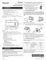
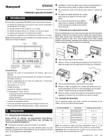
RTH2520
Programmable Thermostat
Installation and User Guide
Adjustment
buttons
Display
System operating
mode selector
Fan operating
mode selector
Backlight
button
Programming
buttons
RTH2520 terminals
Description
Wire labels
Rh
Heating power supply
Rh, R, 4, V
Rc
Cooling power supply
Rc, R
W
Heating signal
W, W1, H
Y
Cooling signal
Y, Y1, M
G
Fan
G, F
69-1867ES-05