Honeywell T8034N1007 Installation Instructions
Honeywell T8034N1007 - 1 Stage Horizontal Thermostat Manual
 |
UPC - 085267271295
View all Honeywell T8034N1007 manuals
Add to My Manuals
Save this manual to your list of manuals |
Honeywell T8034N1007 manual content summary:
- Honeywell T8034N1007 | Installation Instructions - Page 1
Thermostat INSTALLATION INSTRUCTIONS APPLICATION The T8034C Thermostat (see Fig. 1) controls 24 to 30 Vac single-stage service technician. 4. After installation is complete, check out the product operation as provided in these instructions. ® U.S. Registered Trademark Copyright © 2001 Honeywell - Honeywell T8034N1007 | Installation Instructions - Page 2
plate assembly is used, review the instructions provided with the assembly before wiring and mounting the thermostat. To wire and mount the thermostat: 1. In replacement applications, check the existing thermostat wires for cracked or frayed insulation. Replace any wires in poor condition. If the - Honeywell T8034N1007 | Installation Instructions - Page 3
THERMOSTAT H1 C1 TEMP. FALL H1 ANTICIPATOR FAN SWITCH ON AUTO C1 ANTICIPATOR SYSTEM SWITCH COOL OFF HEAT 1 POWER SUPPLY. PROVIDE DISCONNECT MEANS AND OVERLOAD PROTECTION AS REQUIRED. 2 IN SINGLE the ammeter, reconnect the W wire, and mount the thermostat. NOTE: For best performance, - Honeywell T8034N1007 | Installation Instructions - Page 4
. Place the System switch to the Off position. Wait at least five minutes. 2. Remove the thermostat cover. Move the setting lever until the switch just makes contact. (The mercury in the switch U.S.A. on recycled paper containing at least 10% post-consumer paper fibers. www.honeywell.com/yourhome
-
 1
1 -
 2
2 -
 3
3 -
 4
4
 |
 |
fi U.S. Registered Trademark
Copyright ' 2001 Honeywell °
° All Rights Reserved
INSTALLATION INSTRUCTIONS
69-1596
T8034C Heating and
Cooling Thermostat
APPLICATION
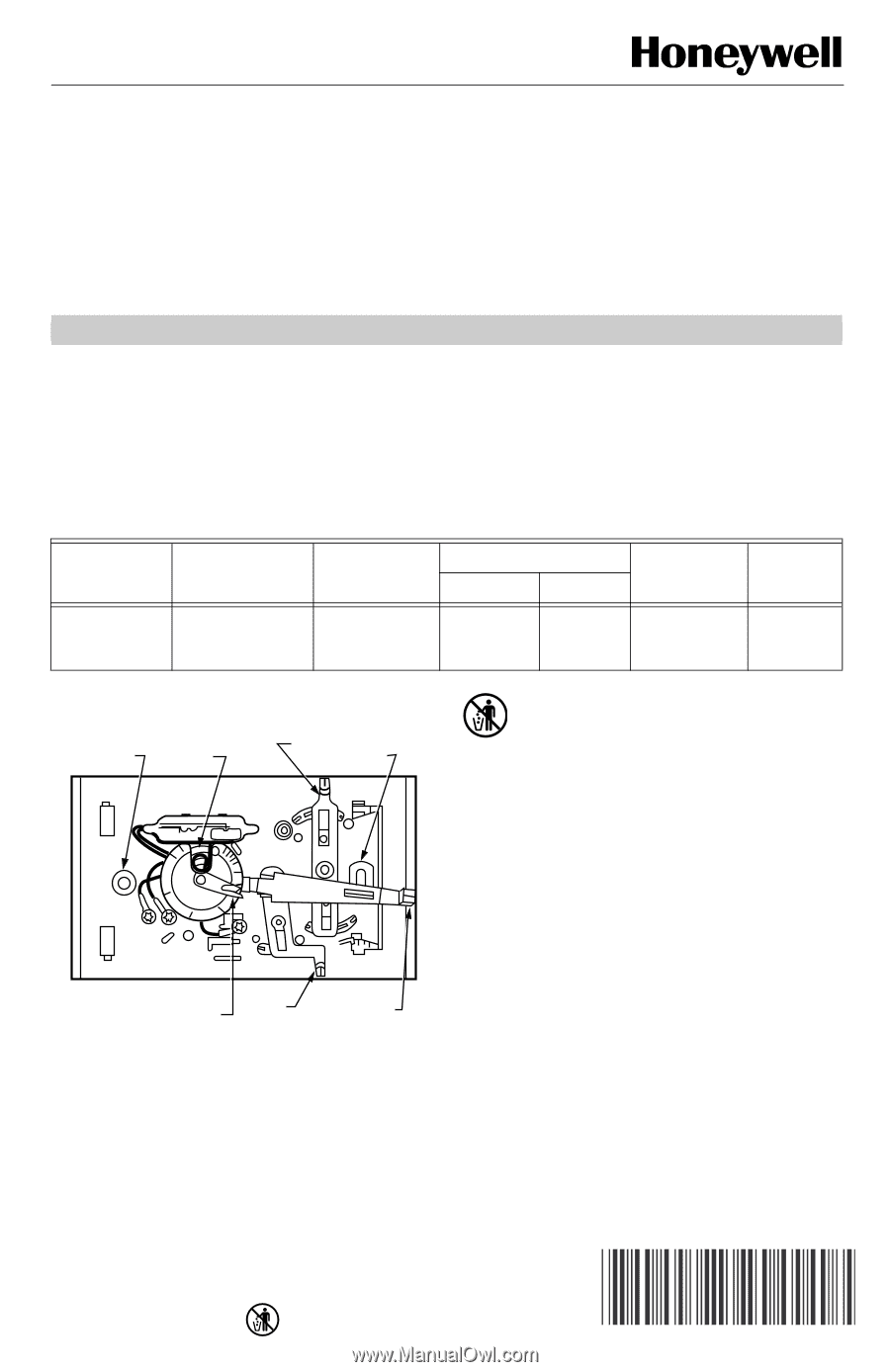
The T8034C Thermostat (see Fig. 1) controls 24 to 30 Vac single-stage heating-cooling systems. See Table 1 for
application information. An spdt mercury switch makes R to W on a temperature fall for heating, and R to Y on a
temperature rise for cooling.
Fig. 1. T8034C internal view.
MERCURY NOTICE
If this control is replacing a control that contains
mercury in a sealed tube, do not place your old
control in the trash. Dispose of properly.
Contact your local waste management authority
for instructions regarding recycling and the
proper disposal of an old control.
INSTALLATION
When Installing This Product . . .
1.
Read these instructions carefully. Failure to follow
them could damage the product or cause a hazard-
ous condition.
2.
Check the ratings given in the instructions and on
the product to make sure the product is suitable for
your application.
3.
Installer must be a trained, experienced service
technician.
4.
After installation is complete, check out the product
operation as provided in these instructions.
Table 1. T8034C Specifications.
Model No.
Application
Heat
Anticipation
Switching
Comments
See Fig.
No.
System
Fan
T8034C1085
For use in gas- or
oil-fired heating
systems.
0.18A to 1.0A,
adjustable.
Heat-Off-
Cool
On-Auto
TRADELINEfi
3
MOUNTING HOLE
(THERMOSTAT
TO WALL OR
OUTLET BOX)
BIMETAL ELEMENT
BEHIND HEAT
ANTICIPATOR
SCALE
SYSTEM
SWITCH
MOUNTING
HOLE
TEMPERATURE
SETTING LEVER
FAN
SWITCH
M5601
ADJUSTABLE HEAT
ANTICIPATOR INDICATOR
.25
.3
.35
.5
.7
.9
.2
.18
L
O
N
G