Honeywell T8195B Installation Instructions
Honeywell T8195B Manual
 |
View all Honeywell T8195B manuals
Add to My Manuals
Save this manual to your list of manuals |
Honeywell T8195B manual content summary:
- Honeywell T8195B | Installation Instructions - Page 1
used to directly control a line voltage system. For proper system operation, a Honeywell R841 or R8239D1015 Isolating Relay must be added to the thermostat control circuit. b Consult manufacturer for installation requirements. D.F. • Rev. 11-94 • 1 • ©Honeywell Inc. 1994 • Form Number6699--00556644 - Honeywell T8195B | Installation Instructions - Page 2
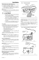
a trained experienced service technician. 3. After installation is complete, check out product op- eration as provided in these instructions. IMPORTANT: An incorrectly leveled subbase will cause the temperature control to deviate from setpoint. It is not a calibration problem. CAUTION 1. Disconnect - Honeywell T8195B | Installation Instructions - Page 3
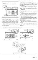
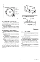
affecting thermostat operation. Subbase (Heating/Cooling Systems) Refer to Fig. 5, and strip the thermostat wire insulation as necessary. Connect the wires to the corresponding terminals on the subbase. If labels do not agree with your new subbase, refer to Table 2 and the installation instructions - Honeywell T8195B | Installation Instructions - Page 4
by the system low-voltage transformer. 24 Vac must be maintained across terminals R and C. Push excess wire back into the wall. Plug the hole in wall with nonhardening caulk, putty, or nonflammable insulation to prevent drafts from affecting thermostat operation. MOUNT THE THERMOSTAT Note the tabs - Honeywell T8195B | Installation Instructions - Page 5
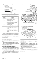
both levers 5° F [3° C] below the room temperature. The burner should shut off. Operate the entire heating system at least one complete cycle. If thermostat fails any test, refer to the Troubleshooting Guide in the Owner's Manual. Reset both the temperature setting levers to the desired temperatures - Honeywell T8195B | Installation Instructions - Page 6
room temperature. The cooling equipment and the fan should shut off. Operate the entire cooling system at least one complete cycle. If thermostat fails any test, refer to the Troubleshooting Guide in the Owner's Manual. Reset both the temperature setting levers to the desired temperatures. HEATING - Honeywell T8195B | Installation Instructions - Page 7
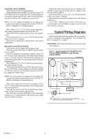
Fig. 12-Typical hookup for T8195B Thermostat and Q682B Subbase in conventional heating/ cooling system. TIMER THERMOSTAT HEAT/COOL ANTICIPATOR H C FALL H C FALL SUBBASE SYSTEM SWITCH FAN SWITCH 2 FILTER LED HEAT OFF COOL ON AUTO HEAT OFF COOL CR B O G W Y X L1 (HOT) L2 HEATING - Honeywell T8195B | Installation Instructions - Page 8
Automation and Control Solutions Honeywell International Inc. Honeywell Limited-Honeywell Limitée 1985 Douglas Drive North 35 Dynamic Drive Golden Valley, MN 55422 Scarborough, Ontario M1V 4Z9
-
 1
1 -
 2
2 -
 3
3 -
 4
4 -
 5
5 -
 6
6 -
 7
7 -
8
 |
 |

D.F.
•
Rev. 11-94
•
•
©Honeywell Inc. 1994
•
Form Number 69-0564—3
T8195B/Q682B,C, Y8224A
Heating or Cooling and Heating/Cooling
New Construction Thermostat,
Wallplate and Subbase
Installation Instructions for the Trained Service Technician.
Preparation
Check thermostat and subbase (if used) suitability for the
heating, cooling, or heating/cooling system. Refer to Table 1.
Assemble tools required: flat bladed screwdriver, hand or
power drill with 3/16-in. drill bit, wire cutter/stripper or
sharp knife, bubble level or plumb bob and line.
Assure power is off to the heating, cooling, or heating/
cooling system at the main fuse panel. Most buildings have
a separate switch box or circuit breaker for disconnecting
power to the heating and cooling (if applicable) equipment.
This thermostat is compatible with most heating, cooling,
or heating/cooling systems. Refer to Table 1 for thermostat
and system compatibility information.
a
If thermostat is not compatible with the system being controlled, the system will not operate. No hazard exists. The thermo-
stat will not be damaged unless it is used to directly control a line voltage system. For proper system operation, a Honeywell
R841 or R8239D1015 Isolating Relay must be added to the thermostat control circuit.
b
Consult manufacturer for installation requirements.
Recycling Notice
This control contains mercury in a sealed tube. Do
not
place control in the trash at the end of its useful life.
If this control is replacing a control that contains mercury
in a sealed tube, do
not
place your old control in the trash.
Contact your local waste management authority for in-
structions regarding recycling and the proper disposal of this
control, or of an old control containing mercury in a sealed
tube.
If you have questions, call Honeywell Inc. at 1-800-
468-1502.
TABLE 1—THERMOSTAT AND SYSTEM COMPATIBILITY.
Type of Heating System
to be Controlled
Conditions/Compatibility
Electric (Line Voltage)—typical
baseboard and radiant
•
The R8239D1015 Isolating Relay or R841 Silent Switching Center must be
installed in the thermostat control circuit.
a
Fan Coil Unit
•
Compatible. Assure correct subbase identity is selected for fan control.
Gas—Direct Spark Ignition
(DSI), Intermittent Pilot (IP), and
Standing Pilot (SP)
•
Compatible. Assure that 24V control transformer common is accessible for
connection to thermostat cable conductor and power to the transformer is not
regularly interrupted by high temperature or limit operation.
Heat Pump
•
Compatible. Assure correct subbase identity is selected for fan control and
changeover control (O terminal for cool and B terminal for heat). Jumper Y
to W for heat pump compressor control.
Hot Water Zone
•
Honeywell 2-wire valves are compatible.
•
Some non-Honeywell 2-wire valves require an R8239D1015 Isolating Relay
in the thermostat control circuit.
a
•
Some 3-wire valves require an R8239A1052 Isolating Relay in the
thermostat control circuit.
a, b
Oil
•
Assure that the 24V control transformer common is accessible for connection
to thermostat cable conductor and power to the transformer is not regularly
interrupted by high temperature, purge cycle, or limit operation.
Vent Damper
•
Honeywell damper motors are compatible.
•
Some non-Honeywell damper motors require an R8239D1015 Isolating
Relay in the thermostat control circuit.
a
Check control amperage
requirement.
Warm Air Zone
•
Most are compatible.