Honeywell T8401C1015 Installation Instructions
Honeywell T8401C1015 - Electronic Thermostat - 1 Heat/1Cool Manual
 |
View all Honeywell T8401C1015 manuals
Add to My Manuals
Save this manual to your list of manuals |
Honeywell T8401C1015 manual content summary:
- Honeywell T8401C1015 | Installation Instructions - Page 1
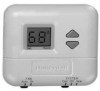
T8401C Electronic Thermostats INSTALLATION INSTRUCTIONS The T8400C and T8401C Thermostats provide singlestage, non-programmable temperature control for 24V heating-cooling systems with manual and T8401C models include a thermostat, wallplate (for wiring and mounting thermostat) and owner's guide. - Honeywell T8401C1015 | Installation Instructions - Page 2
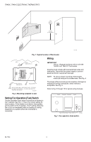
T8401C ELECTRONIC THERMOSTATS YES NO NO 5 FEET [1.5 METERS] NO M11338 Fig. 1. Typical location of thermostat. Wiring WALL 1 WALL ANCHORS (2) IMPORTANT Use an 18-gauge maximum wire to wire the T8400C and T8401C Thermostats fan to turn on immediately with the heating or cooling equipment in a system - Honeywell T8401C1015 | Installation Instructions - Page 3
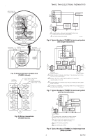
T8400C, T8401C ELECTRONIC THERMOSTATS KEEP WIRING IN SHADED AREA G Rc R W B Y O MOUNTING SCREW L1 (HOT) 24V L2 HEATING PRIMARY CONTROL FAN RELAY 1 POWER SUPPLY. PROVIDE DISCONNECT MEANS AND OVERLOAD PROTECTION AS REQUIRED. 2 FACTORY INSTALLED JUMPER. M13275 Fig. 6. Typical hookup of - Honeywell T8401C1015 | Installation Instructions - Page 4
T8400C, T8401C ELECTRONIC THERMOSTATS G C R W B Y O 1 L1 (HOT) 24V L2 TRANSFORMER HEAT RELAY COOL RELAY FAN RELAY 1 POWER SUPPLY. PROVIDE DISCONNECT MEANS AND OVERLOAD PROTECTION AS REQUIRED. M20881 Fig. 9. Typical hookup of T8401C in heat-cool system. DASHED LINES INDICATE TABS ON - Honeywell T8401C1015 | Installation Instructions - Page 5
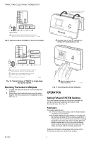
the thermostat to select the desired system setting. INCREASE SETTING DECREASE SETTING T8400C, T8401C ELECTRONIC THERMOSTATS 3. turns it off; if cool is off, ▼ turns it on. M14685 2. Press the ▲▼ keys simultaneously for more than one second to light all segments on display and to enter installer - Honeywell T8401C1015 | Installation Instructions - Page 6
, T8401C ELECTRONIC THERMOSTATS NOTE: In installer setup mode only, each press of the ▲ key momentarily displays 01. Each press of the ▼ key momentarily displays 02. When the keys are released, these two-digit codes are no longer displayed. 3. Press the ▲ key. Factory information is displayed - Honeywell T8401C1015 | Installation Instructions - Page 7
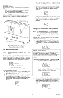
minute delay, see the Optional System Checkout section. T8400C, T8401C ELECTRONIC THERMOSTATS Fan 1. Slide the SYSTEM switch to Off and the FAN switch to On. The fan should run continuously. 2. Slide the FAN switch to Auto. In heating, the fan is controlled directly by the heating equipment and may - Honeywell T8401C1015 | Installation Instructions - Page 8
Automation and Control Solutions Honeywell International Inc. Honeywell Limited-Honeywell Limitée 1985 Douglas Drive North 35 Dynamic Drive Golden Valley, MN 55422 Scarborough, Ontario M1V 4Z9 69-1740 J.S. 6-04 www.honeywell.com/yourhome
-
 1
1 -
 2
2 -
 3
3 -
 4
4 -
 5
5 -
 6
6 -
 7
7 -
8
 |
 |
fi U.S. Registered Trademark
Copyright ' 2004 Honeywell International Inc.
°
° All Rights Reserved
INSTALLATION INSTRUCTIONS
69-1740
T8400C, T8401C
Electronic Thermostats
The T8400C and T8401C Thermostats provide single-
stage, non-programmable temperature control for 24V
heating-cooling systems with manual changeover from
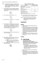
heat to cool. Heating cycle rate is selectable at 1, 3, 4, 5,
6, 9, or 12 cph. Cooling cycle rate is fixed at 3 cph.
Temperature indication can be set for ±F or ±C.
The T8400C Thermostat is powered through the heating/
cooling system controls. The T8401C requires a common
wire for operation. Batteries are not required because
setpoints are held permanently by non-volatile memory.
The T8400C and T8401C models include a thermostat,
wallplate (for wiring and mounting thermostat) and
owner²s guide.
MERCURY NOTICE
If this control is replacing a control that contains
mercury in a sealed tube, do not place your old
control in the trash.
Contact your local waste management authority
for instructions regarding recycling and the
proper disposal of an old control containing
mercury in a sealed tube.
INSTALLATION
When Installing this Product°
1.
Read these instructions carefully. Failure to follow
them could damage the product or cause a hazard-
ous condition.
2.
Check the ratings given in the instructions and on
the product to make sure the product is suitable for
your application.
3.
Installer must be a trained, experienced service
technician.
4.
After installation is complete, check out product
operation as provided in these instructions.
CAUTION
Electrical Shock or Equipment Damage
Hazard.
Can shock individuals or short equipment
circuitry.
Disconnect power supply before installation.
Location
Install the thermostat about 5 ft (1.5m) above the floor in
an area with good air circulation at average temperature.
See Fig. 1. Do not install the thermostat where it can be
affected by:
³ drafts or dead spots behind doors and in corners.
³ hot or cold air from ducts.
³ radiant heat from the sun or appliances.
³ concealed pipes and chimneys.
³ unheated (uncooled) areas such as an outside wall
behind the thermostat.
This thermostat is a precision instrument and was
carefully adjusted at the factory. Handle it carefully.
Mounting Wallplate to Wall
IMPORTANT
Level only for appearance. The thermostat func-
tions normally even when not level.
Mount the T8400C and T8401C with the screws provided
(see Fig. 2) as follows:
1.
Place the wallplate at the desired location on the
wall.
2.
Pull the thermostat wire through the entrance hole
on the wallplate.
3.
Fasten the wallplate to the wall using the anchors
and screws provided.
4.
After wiring the wallplate, plug the hole to prevent
drafts from affecting the thermostat; see Wiring
section.