Honeywell T8775C1005 Installation Instructions
Honeywell T8775C1005 - Digital Round 24V Manual
 |
UPC - 085267244183
View all Honeywell T8775C1005 manuals
Add to My Manuals
Save this manual to your list of manuals |
Honeywell T8775C1005 manual content summary:
- Honeywell T8775C1005 | Installation Instructions - Page 1
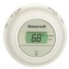
T8775A,C The Digital Round™ Non-Programmable Thermostats The T8775A,C Thermostats provide single-stage temperature control for 24V systems. The T8775A,C models include a thermostat, wallplate (for wiring and mounting thermostat), mounting screws, wall anchors, and a 4074 FAB resistor. MERCURY - Honeywell T8775C1005 | Installation Instructions - Page 2
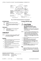
T8775A,C THE DIGITAL ROUND™ NON-PROGRAMMABLE THERMOSTATS Wiring IMPORTANT Use 18-gauge wire to wire the T8775A,C Thermostats. All wiring must comply with local electrical codes and ordinances. Disconnect the power supply to prevent electrical shock or equipment damage. Refer to Fig. 2 through 6 for - Honeywell T8775C1005 | Installation Instructions - Page 3
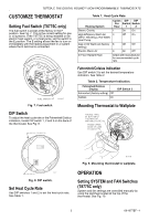
T8775A,C THE DIGITAL ROUND™ NON-PROGRAMMABLE THERMOSTATS CUSTOMIZE THERMOSTAT Setting Fuel Switch (T8775C only) The fuel switch is preset at the factory in the F position. See Fig. 7. This is the correct setting for gas or oil systems. If the T8775C is being installed on an electric heat system, or - Honeywell T8775C1005 | Installation Instructions - Page 4
T8775A,C THE DIGITAL ROUND™ NON-PROGRAMMABLE THERMOSTATS (T8775C ONLY) SELECTS COOL/OFF/HEAT (T8775C ONLY) SELECTS ON/AUTO ROOM SHOWS THAT THE SET CURRENT ROOM TEMPERATURE IS DISPLAYED. DISPLAYS ROOM OR SET TEMPERATURE SHOWS THAT THE CURRENT TEMPERATURE SETPOINT IS DISPLAYED. DISPLAYS AND - Honeywell T8775C1005 | Installation Instructions - Page 5
ronds numériques, non programmables The Digital Round™ T8775A, C Les thermostats T8775A et C assurent la régulation de la température dans les systèmes 24 V à un étage. Ils comprennent un thermostat, une plaque de commutation (pour le câblage et le montage du thermostat), des vis de montage - Honeywell T8775C1005 | Installation Instructions - Page 6
THERMOSTATS RONDS NUMÉRIQUES, NON PROGRAMMABLES THE DIGITAL ROUND™ T8775A,C CHEVILLES D'ANCRAGE (2) PLAQUE DE COMMUTATION 1 TROU DE CÂBLAGE VIS 1 PO (2) 1 DANS LE CAS D'UNE INSTALLATION AVEC CHEVILLES D'ANCRAGE, PERCER DES TROUS DE 3/16 PO SI LE MUR EST EN PLACOPLTRE OU DE 7/32, SI LE MUR EST - Honeywell T8775C1005 | Installation Instructions - Page 7
, NON PROGRAMMABLES THE DIGITAL ROUND™ T8775A,C B Rc 2 G R Y W CONTACTEUR DU COMPRESSEUR RELAIS DE RELAIS DE 1 CHAUFFAGE OU BOBINE DE VANNE VENTILATEUR 1 1 ALIMENTATION. FOURNIR AU BESOIN UN DISPOSITIF DE COUPURE ET UNE PROTECTION CONTRE LES SURCHARGES. 2 ENLEVER LE CAVALIER INSTALL - Honeywell T8775C1005 | Installation Instructions - Page 8
NUMÉRIQUES, NON PROGRAMMABLES THE DIGITAL ROUND™ T8775A,C Tableau 2. Affichage de la température. Affichage en Celsius ou Fahrenheit Fahrenheit (réglé en usine) Celsius Microrupteur 3 Off On ON 123 Montage du thermostat sur une plaque de commutation MICRORUPTEURS MF19567 Fig. 8. Microrupteurs - Honeywell T8775C1005 | Installation Instructions - Page 9
THERMOSTATS RONDS NUMÉRIQUES, NON PROGRAMMABLES THE DIGITAL ROUND™ T8775A,C (T8775C SEULEMENT) SÉLECTION DE COOL, OFF OU HEAT (T8775C SEULEMENT) SÉLECTION DE ON OU AUTO ROOM INDIQUE QUE LA SET TEMPÉRATURE AMBIANTE ACTUELLE EST AFFICHÉE. AFFICHAGE DE LA TEMPÉRATURE AMBIANTE OU - Honeywell T8775C1005 | Installation Instructions - Page 10
RONDS NUMÉRIQUES, NON PROGRAMMABLES THE DIGITAL ROUND™ T8775A,C 3. Au bout de cinq minutes environ, un flocon de neige apparaîtra sur le thermostat. Le système de refroidissement devrait se mettre en marche. 4. Régler le point de consigne à une température supérieure à la température ambiante - Honeywell T8775C1005 | Installation Instructions - Page 11
7 69-1677EF-1 - Honeywell T8775C1005 | Installation Instructions - Page 12
Solutions de régulation et d'automatisation Honeywell International Inc. Honeywell Limited-Honeywell Limitée 1985 Douglas Drive North 35, Dynamic Drive Golden Valley, MN 55422 Scarborough (Ontario) M1V 4Z9 69-1677EF-1 J.S. Rév. 6-04 Imprimè au Hungary www.honeywell.com/yourhome
-
 1
1 -
 2
2 -
 3
3 -
 4
4 -
 5
5 -
 6
6 -
 7
7 -
8
-
9
-
10
-
11
-
12
 |
 |
INSTALLATION INSTRUCTIONS
fi U.S. Registered Trademark
° Patents Pending
' 2004 Honeywell International Inc.
All Rights Reserved
69-1677EF±1
T8775A,C
The Digital Round
™
Non-Programmable Thermostats
The T8775A,C Thermostats provide single-stage
temperature control for 24V systems. The
T8775A,C models include a thermostat, wallplate
(for wiring and mounting thermostat), mounting
screws, wall anchors, and a 4074 FAB resistor.
MERCURY NOTICE
If this control is replacing a control that
contains mercury in a sealed tube, do not
place your old control in the trash.
Contact your local waste management
authority for instructions regarding
recycling and the proper disposal of an old
control containing mercury in a sealed
tube.
INSTALLATION
When Installing this Product°
1.
Read these instructions carefully. Failure to
follow them could damage the product or
cause a hazardous condition.
2.
Check the ratings given in the instructions
and on the product to make sure the product
is suitable for your application.
3.
Installer must be a trained, experienced ser-
vice technician.
4.
After installation is complete, check out prod-
uct operation as provided in these instruc-
tions.
CAUTION
Electrical Shock or Equipment Damage
Hazard.
Can shock individuals or short
equipment circuitry.
Disconnect power supply before
installation.
Location
Install the thermostat about 5 ft (1.5m) above the
floor in an area with good air circulation at average
temperature. Do not install the thermostat where it
can be affected by:
± drafts or dead spots behind doors and in
corners.
± hot or cold air from ducts.
± radiant heat from the sun or appliances.
± concealed pipes and chimneys.
± unheated (uncooled) areas such as an outside
wall behind the thermostat.
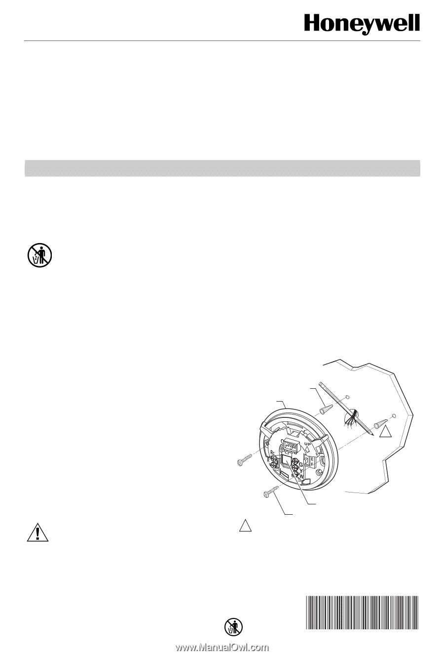
Mounting Wallplate to Wall
Mount the T8775A,C wallplate, with the screws
provided. See Fig. 1.
Fig. 1. Mounting wallplate to wall.
M19499
WALL ANCHORS (2)
WIRING HOLE
WALL PLATE
1 INCH SCREW (2)
1
WHEN USING WALL ANCHORS, DRILL 3/16 IN. HOLES
FOR DRYWALL, 7/32 IN. HOLES FOR PLASTER.
1