Honeywell TB6575B1000/U Installation Instructions
Honeywell TB6575B1000/U - SuitePro Digital Fan Coil Stat Manual
 |
View all Honeywell TB6575B1000/U manuals
Add to My Manuals
Save this manual to your list of manuals |
Honeywell TB6575B1000/U manual content summary:
- Honeywell TB6575B1000/U | Installation Instructions - Page 1
Fan Coil thermostats for residential and commercial applications such as hotels, condominiums, school classrooms, etc. Three models are available for your application: • TB6575A1000 - 2-pipe or 4-pipe with seasonal/ manual/automatic heat/cool changeover; 120/240 Vac. • TB6575B1000 - 2-pipe only - Honeywell TB6575B1000/U | Installation Instructions - Page 2
page 5 for fly lead usage. Minimum Operational Life (at maximum load): Thermostat contacts: 100,000 cycles Approvals: CSA Certified C/US for Canada and the or 240 Vac TB6575B1000 Heat or 2 Cool 120 or 240 Vac TB8575A1000 All 2 or 4 24 Vac Features Number Energy Fan: On, Manual/ Remote Back - Honeywell TB6575B1000/U | Installation Instructions - Page 3
instructions carefully. Failure to follow them could damage the product or cause a hazardous condition. 2. Check the ratings given in the instructions before servicing. IMPORTANT The thermostats the supply wires: a. For the TB6575A1000 and TB6575B1000 models: (1) Push the fly lead wires through the - Honeywell TB6575B1000/U | Installation Instructions - Page 4
TO A 4X4 WIRING BOX. M27591 Fig. 3. Mounting sub-base and thermostat using the adaptor plate (50033847-001). Terminal Wiring Table 3 provides the terminal wiring for each model and application. NOTE: The TB6575A1000 and TB6575B1000 models have color coded fly leads attached to the terminals - Honeywell TB6575B1000/U | Installation Instructions - Page 5
• SB: Remote setback (optional) TB6575/TB8575 DIGITAL FAN COIL THERMOSTATS • Sc: Ground (required if remote sensor, pipe sensor, and 9 9 O R O 9 4 pipes; Heat and Cool with Manual Changeover or Auto Changeover 9 W Y 99 9 9 ORO TB6575B1000 - 120/240 Vac Terminal Identifier L W/Y n/ai Gl Gm Gh - Honeywell TB6575B1000/U | Installation Instructions - Page 6
complete wiring instructions, please follow the installation instructions provided with or death. Disconnect power supply before servicing. M27559 Fig. 4. Wiring four TR21 depending on the application. - The maximum length of wire from the thermostat to a wall module is 1000 ft. (305 m). - Twisted - Honeywell TB6575B1000/U | Installation Instructions - Page 7
this section illustrate typical wiring for: • TB6575A1000 and TB6575B1000 fan coil thermostats, which are 120/240 Vac powered. Refer to Fig Sc SB REMOTE SETBACK Ps M27570 Fig. 11. Four pipes (Heat and Cool) Manual/Auto changeover wiring diagram (120/240 Vac shown). L L (HOT) W/Y VALVE - Honeywell TB6575B1000/U | Installation Instructions - Page 8
TB6575/TB8575 DIGITAL FAN COIL THERMOSTATS . L W/Y Y/A GI 1 Gm Gh 2 N Rs Sc SB Ps HEAT VALVE COOL VALVE L (HOT) 5 FAN 3 REMOTE SENSOR MEANS AND OVERLOAD PROTECTION AS REQUIRED. M27575 Fig. 16. Two pipes (Heat or Cool) Manual Changeover wiring diagram (24 Vac shown). 62-0311-05 8 - Honeywell TB6575B1000/U | Installation Instructions - Page 9
. M27577 Fig. 18. Four pipes (Heat and Cool) Manual/Auto Changeover wiring diagram (24 Vac shown). R W/Y VALVE servicing. CAUTION Equipment damage hazard. Improper removal can damage the thermostat. Carefully follow the thermostat removal directions. If it is necessary to remove the thermostat - Honeywell TB6575B1000/U | Installation Instructions - Page 10
Heat System Fan Fan On Auto M27592 Fig. 21. Removing the thermostat. SETUP The thermostat provides an LCD display, two buttons below the display for System LCD display showing default screen. Power-up At power-up, the thermostat's LCD shows all display segments for two seconds, enters a self- - Honeywell TB6575B1000/U | Installation Instructions - Page 11
DIGITAL FAN COIL THERMOSTATS M27585 Fig. 2.5 Fan On/Off Selection for Aux Heat On 7 Four pipes: Manual and Auto Changeover (Default) 0 Fan ON when Auxiliary Heat is on TB6575A, TB8575A only TB6575A, TB8575A only Allows auxiliary heat to turn on when pipes have cold water (TB6575A, TB8575A only). - Honeywell TB6575B1000/U | Installation Instructions - Page 12
TB6575/TB8575 DIGITAL FAN COIL THERMOSTATS Table 4. Installer Setup (ISU) Codes and Options. (Continued) ISU Option Option Description (Default value shown in Code Code Description Value Bold) 8.5 Fan Speed at motor 0 - Honeywell TB6575B1000/U | Installation Instructions - Page 13
UnOccupied to Occupied; 30 minute delay going from Occupied to UnOccupied. 5 Button Press (Default) Press and hold "Heat/Cool/ Off" button for 3 seconds and thermostat will go into "Economy Setback" 20 Remote Setback for 50 to Range is 50°F to 70°F. Default is 64°F. Heating 70 Used when the - Honeywell TB6575B1000/U | Installation Instructions - Page 14
LCD displays ECONOMY SETBACK just to the right of the main temperature display to indicate the Setback is active. When any key is pressed, the thermostat controls to Occupied mode. REMOTE SETBACK (ISU CODE #19) Remote Setback is activated by a dry contact closure on the remote setback input from an - Honeywell TB6575B1000/U | Installation Instructions - Page 15
to summer months. When using a pipe sensor as an analog input, the thermostat can use the logic below to determine what mode to operate in. A changeover still between the two thresholds, the valve output will be disabled and only manual fan will be available. It will stay in this operation until the - Honeywell TB6575B1000/U | Installation Instructions - Page 16
-energizes during purges. Purge Cycles for 2 Pipe Seasonal Changeover Applications For 2 Pipe with Auto Changeover and 2 Pipe with Auxiliary Heat applications, the thermostat will run purge cycles to determine if there is hot or cold water in the pipes. A 5 minute purge will occur every 2 hours to - Honeywell TB6575B1000/U | Installation Instructions - Page 17
THERMOSTATS TROUBLESHOOTING Table 8 provides troubleshooting information. Table 8. Troubleshooting. Symptom Possible Cause Action Display does not come on. Thermostat operation of equipment in Installer Test mode. Heat does not turn on Heating equipment failure. For TB6575A/B: (Heat On is - Honeywell TB6575B1000/U | Installation Instructions - Page 18
COIL THERMOSTATS Table 8. Troubleshooting. (Continued) Symptom Possible Cause Action Cooling does not turn thermostat is func- tional. Loose connection or broken wire between thermostat and cooling equipment. If voltage is present, check the cooling equipment to find the cause of the problem - Honeywell TB6575B1000/U | Installation Instructions - Page 19
TB6575/TB8575 DIGITAL FAN COIL THERMOSTATS Table 8. Troubleshooting. (Continued) Symptom Possible Cause Action Activity Sensing does All buttons are locked. not exit when button pressed Make sure keypad lockout is disabled. Set ISU - Honeywell TB6575B1000/U | Installation Instructions - Page 20
FAN COIL THERMOSTATS Automation and Control Solutions Honeywell International Inc. 1985 Douglas Drive North Golden Valley, MN 55422 Honeywell Limited-Honeywell Limitée 35 Dynamic Drive Toronto, Ontario M1V 4Z9 customer.honeywell.com ® U.S. Registered Trademark © 2010 Honeywell International Inc
-
 1
1 -
 2
2 -
 3
3 -
 4
4 -
 5
5 -
 6
6 -
 7
7 -
8
-
9
-
10
-
11
-
12
-
13
-
14
-
15
-
16
-
17
-
18
-
19
-
20
 |
 |
INSTALLATION INSTRUCTIONS
62-0311-05
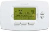
TB6575/TB8575 Digital Fan Coil
Thermostats
PRODUCT DESCRIPTION
The TB6575 and TB8575 are a family of Digital Fan Coil
thermostats for residential and commercial applications
such as hotels, condominiums, school classrooms, etc.
Three models are available for your application:
•
TB6575A1000 – 2-pipe or 4-pipe with seasonal/
manual/automatic heat/cool changeover; 120/240
Vac.
•
TB6575B1000 – 2-pipe only with seasonal or manual
heat/cool changeover; 120/240 Vac.
•
TB8575A1000 – 2-pipe or 4-pipe with seasonal heat/
cool changeover; 24Vac.
All three models are suitable for multiple applications.
Changes in output wiring and external links between
wiring terminals allow you to configure the thermostat for
the appropriate application.
The applications that are available are:
•
Heating or Cooling only
•
Two pipes: Heat or Cool with Manual Changeover
•
Two pipes: Heat or Cool with Seasonal Changeover
(requires optional pipe sensor)
•
Two pipes: Heat or Cool with Auxiliary Heat and
Manual or Seasonal Changeover (requires optional
pipe sensor)
•
Four pipes: Mixed Manual and Auto Changeover
•
Four pipes: Manual Changeover
•
Four pipes: Auto Changeover
The fan is controlled from the thermostat. The Low,
Medium, High, or Auto fan settings are easily made with
a press of a key.
Valves and auxiliary electric heaters can be controlled
using a relay or contactor controlled by the system
switch.
FEATURES
•
Simple, intuitive user interface.
•
Pre-installed lead wires for fast installation
(TB6575A and TB6575B models only)
•
Backlight display permits easy viewing in any
light.
•
Four buttons allow manual control of system
operation, fan speed, and temperature setpoint
adjustment.
•
Digital display of ambient temperature, setpoint,
heating or cooling mode, fan status, and remote
setback
•
Proportional plus Integral (P+I) control algorithm
for precision temperature regulation.
•
Single Setpoint and Heat/Cool setpoint methods
for 4-pipe auto changeover.
•
Adjustable maximum heating and minimum
cooling setpoint limits using range stops.
•
EEPROM permanently retains user settings,
including setpoints, during power loss (no
batteries required).
•
Selectable °C or °F display via Setup button on
thermostat.
•
Displayable pipe sensor temperature readout to
aid in troubleshooting.
•
Selectable to allow the fan motor to always begin
on high speed to ensure sufficient torque at
startup.
•
Option to wire a remote indoor temperature
sensor.
•
Freeze protect algorithm turns on heat when
needed.
•
Economy Setback options via dry contact or
Activity Sensing
•
Advanced fan control with VersaSpeed™ fan ramp
algorithm and Auto Fan Reset
Contents
Product Description
...................................................
1
Features
....................................................................
1
Specifications
............................................................
2
Installation
.................................................................
3
Setup
.........................................................................
10
Operation
...................................................................
14
Troubleshooting
.........................................................
17