Honeywell TB7100A1000 Installation Instructions
Honeywell TB7100A1000 - MultiPro Commercial Thermostat Manual
 |
View all Honeywell TB7100A1000 manuals
Add to My Manuals
Save this manual to your list of manuals |
Honeywell TB7100A1000 manual content summary:
- Honeywell TB7100A1000 | Installation Instructions - Page 1
TB7100A1000 MultiPRO™ Multispeed and Multipurpose Thermostat APPLICATION INSTALLATION INSTRUCTIONS The TB7100A1000 MultiPRO™ Multispeed and Multipurpose Thermostat 4 Pipe Fan Coil • PTAC (up to 2 Heat, 1 Cool) Manual or automatic changeover selectable Heat-Off-Cool-Auto Auto, On Low, Medium, High - Honeywell TB7100A1000 | Installation Instructions - Page 2
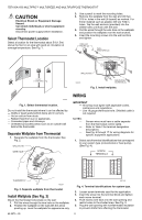
TB7100A1000 MULTIPRO™ MULTISPEED AND MULTIPURPOSE THERMOSTAT CAUTION Electrical Shock or Equipment Damage Hazard. Can shock individuals or short equipment circuitry. Disconnect power supply before installation. Select Thermostat Location Select a location for the thermostat wires through the wire - Honeywell TB7100A1000 | Installation Instructions - Page 3
WIRE TB7100A1000 MULTIPRO™ MULTISPEED AND MULTIPURPOSE THERMOSTAT WALLPLATE WALL OPENING SHADED AREA M22266 Fig. 5. Restrict wires to shaded area of wire hole. Table 2. Terminal Designation Descriptions. Terminal Designation Description RC (see Note 1) Power for cooling-connect to - Honeywell TB7100A1000 | Installation Instructions - Page 4
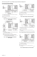
TB7100A1000 MULTIPRO™ MULTISPEED AND MULTIPURPOSE THERMOSTAT Conventional System Wiring L1 1 (HOT) C 3 W1 G G2 Y G3 24 SUPPLY. PROVIDE DISCONNECT MEANS AND OVERLOAD PROTECTION AS REQUIRED. 2 REMOVE FACTORY INSTALLED JUMPER. 3 WHEN USING BATTERIES, THE 24V COMMON CONNECTION IS OPTIONAL. - Honeywell TB7100A1000 | Installation Instructions - Page 5
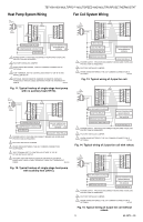
TB7100A1000 MULTIPRO™ MULTISPEED AND MULTIPURPOSE THERMOSTAT Heat Pump System Wiring Fan Coil System Wiring L1 (HOT) 3 24 VAC C W1 L2 G "B" IN THE INSTALLER SETUP. 5 OPTIONAL INDOOR REMOTE SENSOR OR REMOTE SETBACK. WIRES MUST HAVE A CABLE SEPARATE FROM THE THERMOSTAT CABLE. M27421 Fig - Honeywell TB7100A1000 | Installation Instructions - Page 6
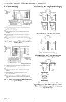
TB7100A1000 MULTIPRO™ MULTISPEED AND MULTIPURPOSE THERMOSTAT PTAC System Wiring Sensor Wiring for Temperature Averaging L1 (HOT) 3 "O" OR "B" IN THE INSTALLER SETUP. 5 OPTIONAL INDOOR REMOTE SENSOR OR REMOTE SETBACK. WIRES MUST HAVE A CABLE SEPARATE FROM THE THERMOSTAT CABLE. M27426 Fig. 16 - Honeywell TB7100A1000 | Installation Instructions - Page 7
TB7100A1000 MULTIPRO™ MULTISPEED AND MULTIPURPOSE THERMOSTAT SUBBASE S1 S2 1 C7189 C7189 2. Locate and remove the tab labeled Remove. See Fig. 23. IMPORTANT This tab must be removed in order to set the real-time clock. C7189 C7189 REMOVE TAB REMOVE DURING INSTALLATION 1 WIRES MUST HAVE A - Honeywell TB7100A1000 | Installation Instructions - Page 8
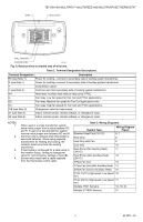
setup screens. See Fig. 25. SETTING DATE/TIME AFTER THERMOSTAT IS ALREADY FUNCTIONING Use the installer setup to set year, month and day. See the Installer Setup Numbers, Settings, and Tests section. YEAR MONTH DAY UP AND DOWN KEYS CHANGES MONTH, DAY, YEAR AND TIME Tue DeSelect Day FanUseEdit - Honeywell TB7100A1000 | Installation Instructions - Page 9
TB7100A1000 MULTIPRO™ MULTISPEED AND MULTIPURPOSE THERMOSTAT INSTALLER SETUP NUMBERS, SETTINGS, AND TESTS (TABLE 4) Configure Installer Setup 1. Press and release the System key. 2. Press System and Done keys simultaneously. 3. Hold keys for approximately five seconds, until the screen changes. 4. - Honeywell TB7100A1000 | Installation Instructions - Page 10
TB7100A1000 MULTIPRO™ MULTISPEED AND MULTIPURPOSE THERMOSTAT Table 4. Installer Setup Menu. (Continued) Installer Setup Number Installer Setup Name Default Setting All Settings Notes 0300 Changeover 1 0-Manual PTAC applications. 0348 Fan Mode 0 0-User can choose To select a particular - Honeywell TB7100A1000 | Installation Instructions - Page 11
TB7100A1000 MULTIPRO™ MULTISPEED AND MULTIPURPOSE THERMOSTAT Table 4. Installer Setup Menu. (Continued) Installer Setup Number Installer Setup Name 0349 Auto Fan Reset Default Setting All Settings 0 0-Inactive 1-Reset back to Auto after 2 hours 2-Reset back to Auto after 4 hours 0535 - Honeywell TB7100A1000 | Installation Instructions - Page 12
TB7100A1000 MULTIPRO™ MULTISPEED AND MULTIPURPOSE THERMOSTAT Installer Setup Number Installer Setup Name 0700 Temperature Display Offset 0710 0720 Restore Factory Defaults Screen Display INSTALLER TESTS Test 1 Installer Test Cool Test 2 Installer Test Fan Test 3 Installer Test Heat Test 4 - Honeywell TB7100A1000 | Installation Instructions - Page 13
TB7100A1000 MULTIPRO™ MULTISPEED AND MULTIPURPOSE THERMOSTAT installer setup selection. The thermostat comes factory default with the fan ramping algorithm enabled (ISU 347). This gives the user . They are manual changeover only. The thermostat will have a changes, system changes, and schedule changes - Honeywell TB7100A1000 | Installation Instructions - Page 14
. Auto-Thermostat automatically changes between heat and cool operation, depending on indoor temperature. Fan Settings Auto -Fan runs only when heating/cooling system is on. On-Fan runs continuously. Table 5 shows default program settings. See Owner's Guide for complete instructions to change the - Honeywell TB7100A1000 | Installation Instructions - Page 15
TB7100A1000 MULTIPRO™ MULTISPEED AND MULTIPURPOSE THERMOSTAT Table 6. Troubleshooting. (Continued) Symptom Possible Cause Action Heat pump puts out cool Changeover Valve (Installer Setup air in the heat mode and Number 0190) is not configured to warm air in the cool match the changeover - Honeywell TB7100A1000 | Installation Instructions - Page 16
TB7100A1000 MULTIPRO™ MULTISPEED AND MULTIPURPOSE THERMOSTAT SPECIFICATIONS Electrical Ratings: Terminal W (Heating) Y (Cooling) G (Fan) Voltage ( /perchlorate Automation and Control Solutions Honeywell International Inc. Honeywell Limited-Honeywell Limitée 1985 Douglas Drive North
-
 1
1 -
 2
2 -
 3
3 -
 4
4 -
 5
5 -
 6
6 -
 7
7 -
8
-
9
-
10
-
11
-
12
-
13
-
14
-
15
-
16
 |
 |
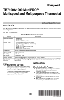
INSTALLATION INSTRUCTIONS
62-0273-05
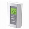
TB7100A1000 MultiPRO™
Multispeed and Multipurpose Thermostat
APPLICATION
The TB7100A1000 MultiPRO™ Multispeed and Multipurpose Thermostat provides electronic control of 24 Vac heating
and cooling systems.
See Table 1 for a description.
Table 1. TB7100A Thermostat Description.
MERCURY NOTICE
If this control is replacing a control that contains
mercury in a sealed tube, do not place your old
control in the trash. Dispose of properly.
Contact your local waste management authority
for instructions regarding recycling and the
proper disposal of an old control.
INSTALLATION
When Installing this Product...
1.
Read these instructions carefully. Failure to follow
them could damage the product or cause a
hazardous condition.
2.
Check ratings given in instructions and on the
product to ensure the product is suitable for your
application.
3.
Installer must be a trained, experienced service
technician.
4.
After installation is complete, check out product
operation as provided in these instructions.
Feature
Description
Powering Methods
•
Battery only
•
24 Vac only
•
24 Vac with battery backup
System Types
•
Conventional (1 Heat, 1 Cool stages)
•
Heat Pump (up to 2 Heat,1 Cool stages)
•
2 Pipe Fan Coil
•
2 Pipe Fan Coil with Auxiliary Heat
•
4 Pipe Fan Coil
•
PTAC (up to 2 Heat, 1 Cool)
Changeover
Manual or automatic changeover selectable
System Setting
Heat-Off-Cool-Auto
Fan Setting
Auto, On
Fan Speeds
Low, Medium, High
Remote Setback
Remote Setback Input for occupancy sensor or DDC setback
Fan Ramping
Algorithm
VersaSpeed™ Fan Ramping Algorithm for automatic fan speed selection (fan coil and PTAC
applications)