Honeywell TB7980B1005 Installation Guide
Honeywell TB7980B1005 - Modulating Thermostat Control Manual
 |
View all Honeywell TB7980B1005 manuals
Add to My Manuals
Save this manual to your list of manuals |
Honeywell TB7980B1005 manual content summary:
- Honeywell TB7980B1005 | Installation Guide - Page 1
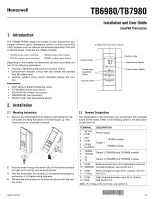
Installation and User Guide ZonePRO Thermostats The TB6980/TB7980 digital thermostats provide proportional plus Instructions 1. Remove the thermostat from its base by unscrewing the captive screw and tilting the bottom of the thermostat up. The screw cannot be completely removed. 2. Pass the wires - Honeywell TB7980B1005 | Installation Guide - Page 2
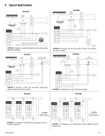
3. Typical Applications TB7980B TB6980B FIGURE 1: Damper control with electric reheat and auxiliary baseboard heating. TB7980B FIGURE 2: Damper control with electric reheat and auxiliary hot-water heating TB6980B FIGURE 3: Damper control with automatic changeover, electric reheat and central - Honeywell TB7980B1005 | Installation Guide - Page 3
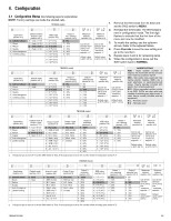
°F (10°C) and ''maximum setpoint - 1'' Default value Default value is 95°F (35°C) is 50°F (10°C) ABBREVIATIONS NSB - Night setback (number of degrees the thermostat will be set back upon receiving a setback signal) SSR - Solid state relay (used with fast cycling electric heaters, SSR's are a quiet - Honeywell TB7980B1005 | Installation Guide - Page 4
Opening time (TB6980 models only) 4.3.1 Default Mode / Output Type The default mode (heat/cool) is used for the following: • The default mode is the thermostat's mode at power-up. • The default mode is the active mode when the N.O. changeover contact is open (see section 5.5.2). • When configured as - Honeywell TB7980B1005 | Installation Guide - Page 5
4.1.) When any setting between 1 and 4 is selected, Output 3 controls heating only, regardless of the thermostat's mode. 4.7 DIP Switches Three switches at the back of the control module are used to select various options. Temperature Display (SW1) Selects the desired temperature display (°C or - Honeywell TB7980B1005 | Installation Guide - Page 6
ML7161A2008, MN7505A2001 Wiring: 18 AWG (1 mm2) wire Mounting: - Honeywell warrants this product, excluding battery, to be free from defects in the workmanship or materials, under normal use and service your thermostat, please go to http://customer.honeywell.com, or call Honeywell technical hotline
-
 1
1 -
 2
2 -
 3
3 -
 4
4 -
 5
5 -
 6
6
 |
 |
TB6980/TB7980
1/6
1. Introduction
The TB6980/TB7980 digital thermostats provide proportional plus
integral individual space temperature control in zoned commercial
HVAC systems such as hydronic and pressure dependent VAV with
or without reheat. There are four different models:
Depending on the models, the thermostat can have up to three out-
puts for the following applications:
Floating or Modulating damper/valve actuator control
Damper/valve actuator control with duct reheat and auxiliary
heat (B models only)
Hydronic systems (room control, perimeter heating and cool-
ing)
Accessories
R841 family of electromechanical relays
T7770A3002 remote room sensor
50014156-002 remote room sensor
32004800-001 bare thermistor
50014157-001 duct temperature sensor
2. Installation
2.1
Mounting Instructions
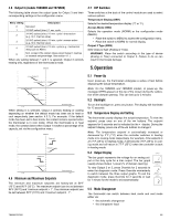
1.
Remove the thermostat from its base by unscrewing the cap-
tive screw and tilting the bottom of the thermostat up. The
screw cannot be completely removed.
2.
Pass the wires through the center hole of the base and secure
the base to the wall or onto an electrical box.
3.
Wire the thermostat. See section 2.2 for terminal designations
and section 3 for typical wiring diagrams.
4.
Reinstall the thermostat onto its base and secure with the cap-
tive screw.
2.2
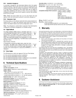
Terminal Designations
The designations of the terminals vary according to the particular
model of thermostat. Refer to the following table for the description
of each terminal.
•
TB7980A (single output, modulating)
•
TB6980A (single output, floating)
•
TB7980B (multiple output modulating)
•
TB6980B (multiple output, floating)
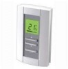
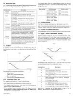
Configuration and status display
Heating mode
Temperature display
Output power display
Temperature
adjustment
button
Cooling mode
Override button
TERMINAL
DESCRIPTION
1
2
24 VAC
COM
Power supply
3
4
AN1
COM
Output 1
TB7980 models
3
4
OPEN
CLOSED
TB6980 models
5
6
T2/AN2
T2/COM
Output 2 (TB6980B and TB7980B models)
7
8
T3
T3
Output 3 (TB6980B and TB7980B models)
9
10
COM
SENSOR
External sensor input. (For applications requiring
an external sensor, see section 4.2.)
9
11
COM
C-Over
Mode Changeover input (N.O. contact). See sec-
tion 5.5.2.
9
12
COM
NSB
Night Setback activation input (N.O. contact).
See section 5.6.
Note
: To configure the terminals, see section 4.
TB6980/TB7980
Installation and User Guide
ZonePRO Thermostats