Hoover F5810 Manual - Page 3
Assemble stair/upholstery nozzle - carpet hose
 |
UPC - 719881157764
View all Hoover F5810 manuals
Add to My Manuals
Save this manual to your list of manuals |
Page 3 highlights
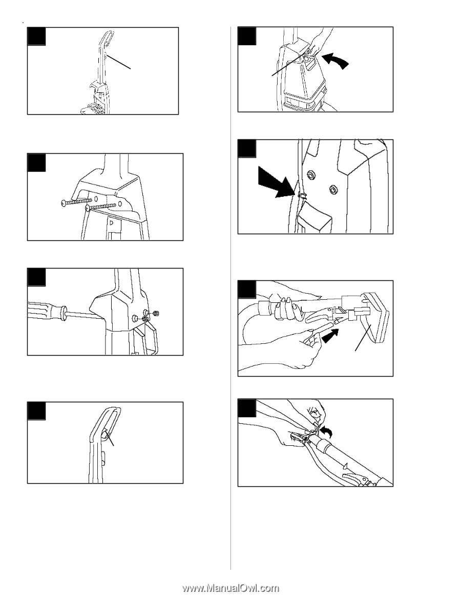
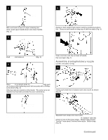
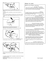
2 CORD HOOK With cord hook to back of carpet cleaning machine, push upper handle down onto lower handle. (Fig. 2). 3 6 TANK HANDLE Replace clean solution tank (upper tank) by positioning bottom first. Press on tank handle to snap top of tank into place (Fig. 6). 7 Push bolts into holes on front of handle (Fig. 3). If bolts will not go through hole easily handle is not pushed completely down. 4 Press cord into cord clip on back of handle. Pull cord tight. (Fig. 7) Assemble stair/upholstery nozzle (some models only) 8 Place nuts in recessed areas on back of handle. Hold each nut in place while tightening each bolt securely with a Phillips screw driver (Fig. 4). Only two nuts are needed on this model. The extra nut is not required but has been provided for your convenience. 5 NOZZLE Firmly push small end of solution tube onto nozzle as shown (Fig. 8) 9 SQUEEZE TRIGGER When handle sections are completely together, squeeze trigger on upper handle to snap trigger rod in place. (Fig. 5) Separate hose straps from each other. Beginning at nozzle end of hose, fit "solution" tube into groove of one of the loose straps. Stretch strap around "suction" hose about 3 inches from nozzle. Button strap (Fig. 9). Continued § Assembly 3
-
 1
1 -
 2
2 -
 3
3 -
 4
4 -
 5
5 -
 6
6 -
 7
7 -
 8
8 -
 9
9 -
10
-
11
-
12
 |
 |