Hotpoint RGB528PENBB Owners Manual - Page 38
eve':ra
 |
View all Hotpoint RGB528PENBB manuals
Add to My Manuals
Save this manual to your list of manuals |
Page 38 highlights
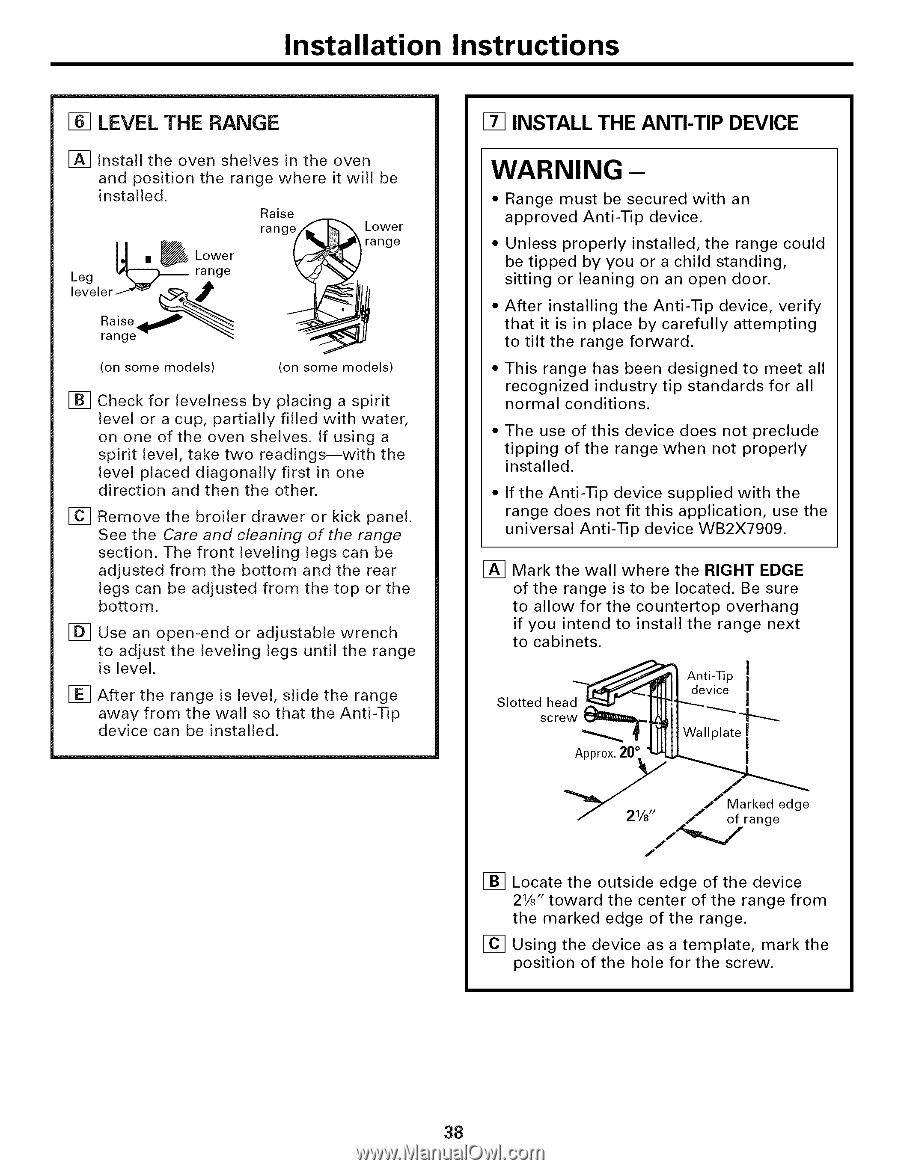
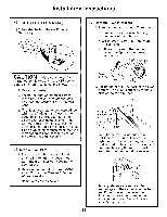
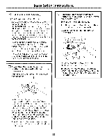
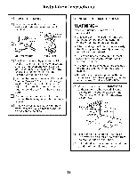
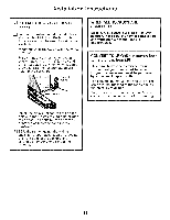
Installation Instructions [] LEVEL THE RANGE [] Install the oven shelves in the oven and position the range where it will be installed. Raise ra n ge/_-'_ Lower ],,] = _Lower range 'eve':ra Leg _ range range -_ (on some models) (on some models) [] Check for levelness by placing a spirit level or a cup, partially filled with water, on one of the oven shelves. If using a spirit level, take two readings--with the level placed diagonally first in one direction and then the other. [] Remove the broiler drawer or kick panel. See the Care and cleaning of the range section. The front leveling legs can be adjusted from the bottom and the rear legs can be adjusted from the top or the bottom. [] Use an open-end or adjustable wrench to adjust the leveling legs until the range is level. [] After the range is level, slide the range away from the wall so that the Anti-Tip device can be installed. [] INSTALL THE ANTI-TIP DEVICE WARNING - • Range must be secured with an approved Anti-Tip device. Unless properly installed, the range could be tipped by you or a child standing, sitting or leaning on an open door. After installing the Anti-Tip device, verify that it is in place by carefully attempting to tilt the range forward. This range has been designed to meet all recognized industry tip standards for all normal conditions. • The use of this device does not preclude tipping of the range when not properly installed. • If the Anti-Tip device supplied with the range does not fit this application, use the universal Anti-Tip device WB2X7909. [] Mark the wall where the RIGHT EDGE of the range is to be located. Be sure to allow for the countertop overhang if you intend to install the range next to cabinets. Slotted head screw Approx. 20 ° Anti-Tip ] device i I Wallplate I I 21/8" Marked edge of range J [] Locate the outside edge of the device 21/J toward the center of the range from the marked edge of the range. [] Using the device as a template, mark the position of the hole for the screw. 38
-
 1
1 -
2
-
3
-
4
-
5
-
6
-
7
-
8
-
9
-
10
-
11
-
12
-
13
-
14
-
15
-
16
-
17
-
18
-
19
-
20
-
21
-
22
-
23
-
24
-
25
-
26
-
27
-
28
-
29
-
30
-
31
-
32
-
 33
33 -
 34
34 -
 35
35 -
 36
36 -
 37
37 -
 38
38 -
 39
39 -
 40
40 -
 41
41 -
 42
42 -
 43
43 -
44
-
45
-
46
-
47
-
48
 |
 |