Hunter 20347 Owner's Manual
Hunter 20347 Manual
 |
View all Hunter 20347 manuals
Add to My Manuals
Save this manual to your list of manuals |
Hunter 20347 manual content summary:
- Hunter 20347 | Owner's Manual - Page 1
For Your Records and Warranty Assistance For reference, also attach your receipt or a copy of your receipt to the manual. Model Name Model No. Date Purchased Where Purchased Type 3 Models Owner's Guide and Installation Manual English Form# 42616-01 20100202 ©2010 Hunter Fan Co. - Hunter 20347 | Owner's Manual - Page 2
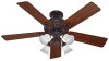
and Cleaning Your Ceiling Fan 17 11 • Troubleshooting 18 Welcome Your new Hunter® ceiling fan is an addition to your home or office that will provide comfort and performance for many years. This installation and operation manual gives you complete instructions for installing and operating - Hunter 20347 | Owner's Manual - Page 3
and safe for your new Hunter fan. If you cannot check off every item, prepare a new fan site as described on this page. Fan Support System • Fan attaches directly to building structure. • Fan support system will hold full weight of the fan and light kit. Ceiling Hole • e outlet box clearance hole - Hunter 20347 | Owner's Manual - Page 4
support service panel. 5-2. read the fan supply line through the outlet box so that the fan supply line extends at least 6" beyond the box. 5-3. Attach the fan ceiling fan site. For instructions to install your ceiling fan, go to your fan manual and continue with Section 2 • Installing the Ceiling - Hunter 20347 | Owner's Manual - Page 5
you maximum installation flexibility and ease. You can install your Hunter fan in one of three ways, depending on ceiling height and your preference: Low Profile, Standard, or Angle mounting. The steps in this manual include instructions for all three Installer's Choice mounting methods. Considering - Hunter 20347 | Owner's Manual - Page 6
, contact your Hunter dealer or call Hunter Technical Support Department at 888-830-1326 (In Canada, call 1-866-268-1936). Preparing the Fan Site Before you begin installing the fan, follow all the instructions in the pullout sheet called "Preparing the Fan Site." Proper ceiling fan location and - Hunter 20347 | Owner's Manual - Page 7
pilot holes into the wood support structure through the outermost holes in the outlet box. The pilot holes should be 9/64" in diameter. For Angled Ceilings: Be sure to orient the ceiling plate so that the two tabs are pointing toward the ceiling peak. 2-2. Your fan comes with four preinstalled - Hunter 20347 | Owner's Manual - Page 8
Set Screw Canopy Canopy Trim Ring WARNING: Fan may fall if not assembled as directed in these installation instructions. 3-1. Unbundle the wires from the fan. For Standard or Angled mounting: 3-2. Insert Locking Screws Locking Screw Low Profile Washer 8 42616-01 • 02/02/10 • Hunter Fan Company - Hunter 20347 | Owner's Manual - Page 9
control device complies with part 15 of the FCC rules. Changes or modifications not expressly approved by Hunter Fan Company could void Hunter Fan speed control supplied with this fan. 4-4. Raise the fan and align the slots in the canopy with the hooks on the ceiling plate. Note: To hang the fan - Hunter 20347 | Owner's Manual - Page 10
wires and wire connectors, except for the white antenna wire from the receiver, back through the ceiling plate into the outlet box. 5-7. Position the receiver in the canopy so that the antenna is close to the edge of the ceiling plate for clear reception. 10 42616-01 • 02/02/10 • Hunter Fan Company - Hunter 20347 | Owner's Manual - Page 11
ball groove. Note: Your fan may have multiple tabs and grooves that must be aligned. 6-2. Swing the fan up to align the canopy screw holes with the mounting holes on the ceiling plate. WARNING: The slots 6-2 Step 6-3 Canopy Canopy Trim Ring 11 42616-01 • 02/02/10 • Hunter Fan Company Canopy Screw - Hunter 20347 | Owner's Manual - Page 12
. Insert the second blade mounting screw, then securely tighten both mounting screws. Step 7-1 (Detail) Grommet Note: The blades on this fan have been treated with Hunter's Dust Armor protection, making the blades less likely to attract dust and dirt. Use a dry or slightly damp lint free cloth to - Hunter 20347 | Owner's Manual - Page 13
Hunter fan comes with an integrated light fixture assembly and an optional switch housing cap and plug button. This feature gives you the option of installing the fan . WARNING: Use only the light fixture supplied with this fan model. 8-1. To attach the upper switch housing, partially install - Hunter 20347 | Owner's Manual - Page 14
Assembly Screw Thumbscrews Note: In compliance with U.S. Federal energy regulations, this ceiling fan contains a wattage saver that restricts the light kit to a maximum of operating properly, see the troubleshooting section. Shade Bulb Steps 8-8 - 8-10 14 42616-01 • 02/02/10 • Hunter Fan Company - Hunter 20347 | Owner's Manual - Page 15
connector (male) through first, and then pull the other plug connector (female) through the hole. 8-17. Install the dummy terminals (included in the sack parts) on the two disconnected wires in the lower switch housing. 8-18. Install the switch housing cap and plug button to the lower switch housing - Hunter 20347 | Owner's Manual - Page 16
holder to any toggle switch plate with the screws already in the switch plate. Or, you can simply mount the remote holder on the wall. Fan Speed High Fan Speed Low Fan Speed Medium Fan Off Fan Light Steps 9-1 - 9-2 16 42616-01 • 02/02/10 • Hunter Fan Company Step 9-4 - Hunter 20347 | Owner's Manual - Page 17
cold weather, having the fan draw air upward (clockwise blade rotation) will distribute the warmer air trapped at the ceiling around the room without will damage the finish. 10-4.T he blades on this fan have been treated with Hunter's Dust Armor protection, making the blades less likely to attract - Hunter 20347 | Owner's Manual - Page 18
Problem: Excessive wobbling. 1. If your fan wobbles when operating, use the enclosed balancing kit and instructions to balance the fan. 2. Tighten all blade and/or blade iron screws. 3. Turn power off, support fan the light sockets. If you need parts or service assistance, please call 888‑830‑1326
-
 1
1 -
 2
2 -
 3
3 -
 4
4 -
 5
5 -
 6
6 -
 7
7 -
8
-
9
-
10
-
11
-
12
-
13
-
14
-
15
-
16
-
17
-
18
 |
 |

Type 3 Models
Type 3 Models
Type 3 Models
Form# 42616-01
20100202
©2010 Hunter Fan Co.
For Your Records and
Warranty Assistance
For reference, also attach your receipt or a copy
of your receipt to the manual.
__________________________________________
Model Name
__________________________________________
Model No.
__________________________________________
Date Purchased
__________________________________________
Where Purchased
English
Owner’s Guide and Installation Manual