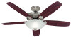
Hunter 20578 Owner's Manual
Hunter 20578 Manual
 |
View all Hunter 20578 manuals
Add to My Manuals
Save this manual to your list of manuals |
Hunter 20578 manual content summary:
- Hunter 20578 | Owner's Manual - Page 1
- Hunter 20578 | Owner's Manual - Page 2
- Hunter 20578 | Owner's Manual - Page 3
- Hunter 20578 | Owner's Manual - Page 4
- Hunter 20578 | Owner's Manual - Page 5
the Fan...11 6 • Installing the Ceiling Plate Cover...13 7 • Assembling the Blades...14 8 • Activating Auto BalanceTM...15 9 • Completing Your Installation With a Bowl Light Fixture...16 10 • Removing the Light Fixture...19 11 • Operation & Maintenance...21 1 42798-01 • 12/28/09 • Hunter Fan Company - Hunter 20578 | Owner's Manual - Page 6
or masonry bit (used only for concrete ceilings) Allen Wrench Wrench Hammer Tape Measure WARNING! • READ AND SAVE THESE INSTRUCTIONS. • Use only Hunter replacement parts. • To reduce the risk of personal injury, attach the fan directly to the support structure of the building according to these - Hunter 20578 | Owner's Manual - Page 7
and safe for your new Hunter fan. If you cannot check off every item, prepare a new fan site as described on this page. Fan Support System • Fan attaches directly to building structure. • Fan support system will hold full weight of the fan and light kit. Ceiling Hole • e outlet box clearance hole - Hunter 20578 | Owner's Manual - Page 8
support service panel. 5-2. read the fan supply line through the outlet box so that the fan supply line extends at least 6" beyond the box. 5-3. Attach the fan ceiling fan site. For instructions to install your ceiling fan, go to your fan manual and continue with Section 2 • Installing the Ceiling - Hunter 20578 | Owner's Manual - Page 9
a tag, to the service panel. Drill two 9/64" pilot holes into the wood support structure through the outermost holes in the outlet box. 71 2.3 2.4 2 2 Your ceiling mounting plate (2) comes the hole in the middle of the ceiling mounting plate (2). 5 42798-01 • 12/28/09 • Hunter Fan Company - Hunter 20578 | Owner's Manual - Page 10
slotted holes in the ceiling mounting plate (2) with the pilot holes you drilled in the wood support structure. For proper alignment ceiling peak. Unbundle the wires from the fan. Note: Your Hunter fan comes with an optional pipe/ball assembly extension pipe. If you are hanging the fan on a ceiling - Hunter 20578 | Owner's Manual - Page 11
(3) with the hooks on the ceiling mounting plate (2). Note: To hang the fan, you must tilt the ceiling mounting plate cover (3) to an almost vertical position so that the ceiling mounting plate cover (3) slots sit on the ceiling mounting plate hooks. 7 42798-01 • 12/28/09 • Hunter Fan Company - Hunter 20578 | Owner's Manual - Page 12
(continued) 3.5 3.6 Extension Pipe Place the slots over the hooks to hang the fan. Pipe 3.7 Ball Pipe Ball Screw Optional Pipe/Ball Instructions: Your Hunter fan comes with an optional pipe/ball assembly extension pipe. If you would like to use the enclosed optional 6 inch pipe/ball assembly - Hunter 20578 | Owner's Manual - Page 13
3.9 3 • Assembling and Hanging the Fan (continued) Ground Wire 3.10 Optional Pipe/Ball Instructions: Remove the screw and ground wire from the pipe. Optional Pipe/Ball Instructions: Reassemble the ground wire, wedge, pin ) are in the battery compartment. 9 42798-01 • 12/28/09 • Hunter Fan Company - Hunter 20578 | Owner's Manual - Page 14
battery recycling center for proper battery disposal information. 10 The remote control device complies with part 15 of the FCC rules. Changes or modifications not expressly approved by Hunter Fan Company could void your authority to operate this equipment. Operation is subject to the following - Hunter 20578 | Owner's Manual - Page 15
5 • Wiring the Fan WARNING!: All wiring must be in accordance with national and local a large wire connector (70), connect the ground wire (grounding) from the ceiling to the green ground wire (grounding) from the ceiling mounting plate and the green ground wire from the pipe/ball assembly (7). 11 - Hunter 20578 | Owner's Manual - Page 16
ceiling to the black wire from the receiver (marked on red tag "LIVE IN") Using the small wire connectors (70), connect the wires from the fan as follows: • The black wire with a white stripe from the fan connect the wire from the fan as follows: • The white wire from the fan to the white wire from - Hunter 20578 | Owner's Manual - Page 17
. The ceiling mounting plate cover trim ring will snap and lock into place. Should you need to remove the trim ring, press firmly on opposite sides of the trim ring (4). The tabs will flex out releasing the ceiling mounting plate cover trim ring (4). 13 42798-01 • 12/28/09 • Hunter Fan Company - Hunter 20578 | Owner's Manual - Page 18
the blade-to-arm screws (47). Tighten the blade-to-arm screws (47) as tight as possible with a screwdriver. 14 42798-01 • 12/28/09 • Hunter Fan Company - Hunter 20578 | Owner's Manual - Page 19
one of the red retaining screws is visible through the notch in the mounting plate. Remove the retaining screw from the bottom of the fan housing using a screwdriver. Repeat this process for all 5 retaining screws. If you are using a pipe/ball assembly longer than 6 inches, leave the retaining - Hunter 20578 | Owner's Manual - Page 20
firmly situated in the narrow end of the keyhole slots. Install the remaining screw into the housing. Tighten all three screws firmly. Your Hunter fan comes with an integrated light fixture assembly and an optional switch housing cap and plug button. This feature gives you the option of installing - Hunter 20578 | Owner's Manual - Page 21
cause improper operation and 31 damage to the product. 30 131 Connect the upper plug connector from the fan body to the lower plug connector in the lower switch housing assembly (31). Place the lower switch housing through the holes in the metal disc. 17 42798-01 • 12/28/09 • Hunter Fan Company - Hunter 20578 | Owner's Manual - Page 22
with the screws already in the switch plate. Or, you can simply mount the remote holder on the wall. 18 42798-01 • 12/28/09 • Hunter Fan Company - Hunter 20578 | Owner's Manual - Page 23
Bowl Light Fixture (cont.) After your installation is complete, restore power to the fan. Wash your hands after installing the fan. 10 • Removing the Light Fixture 10.1 10.2 Removing the Light Fixture Disconnect center of the lower switch housing. 19 42798-01 • 12/28/09 • Hunter Fan Company - Hunter 20578 | Owner's Manual - Page 24
the lower switch housing. Attach the lower switch housing to the upper switch housing with three housing assembly screws. 20 42798-01 • 12/28/09 • Hunter Fan Company - Hunter 20578 | Owner's Manual - Page 25
on the light socket. Problem: Lights shut off suddenly 1. Turn the power to the fan off at the wall switch. Wait 30 seconds, then resume power to the fan.If you have tried these troubleshooting solutions and still have trouble, visit our Web site at: http://www.hunterfan.com. Hunter Fan Company 7130 - Hunter 20578 | Owner's Manual - Page 26
qualified Hunter ceiling fan! With this purchase, you are doing your part to protect the environment. In 2010, ENERGY STAR qualified ceiling fans are ceiling fans save energy because they have more efficient fan motors and air delivery due to more aerodynamic blade configurations. Ceiling fan models
-
 1
1 -
 2
2 -
 3
3 -
 4
4 -
 5
5 -
 6
6 -
 7
7 -
8
-
9
-
10
-
11
-
12
-
13
-
14
-
15
-
16
-
17
-
18
-
19
-
20
-
21
-
22
-
23
-
24
-
25
-
26
 |
 |
