Hunter 21313 Owner's Manual
Hunter 21313 Manual
 |
View all Hunter 21313 manuals
Add to My Manuals
Save this manual to your list of manuals |
Hunter 21313 manual content summary:
- Hunter 21313 | Owner's Manual - Page 1
and Warranty Assistance For reference, also attach your receipt or a copy of your receipt to the manual. Model Name Model No. Catalog No. Date Purchased Where Purchased Type 2 Models Owner's Guide and Installation Manual English Español Form# 42666-01 20081029 ©2008 Hunter Fan Co. - Hunter 21313 | Owner's Manual - Page 2
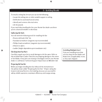
Cleaning Your Ceiling Fan 14 9 • Troubleshooting 15 Welcome Your new Hunter® ceiling fan is an addition to your home or office that will provide comfort and performance for many years. This installation and operation manual gives you complete instructions for installing and operating your fan. We - Hunter 21313 | Owner's Manual - Page 3
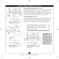
, follow the instructions included with each product. For quiet and optimum performance of your Hunter fan, use only Hunter speed controls. Support Brace Ceiling Outlet Box For ceilings higher than 8 feet, you can purchase Hunter extension downrods. All Hunter fans use sturdy 3/4" diameter - Hunter 21313 | Owner's Manual - Page 4
missing or damaged, contact your Hunter dealer or call Hunter Technical Support Department at 888-830-1326. Preparing the Fan Site Before you begin installing the fan, follow all the instructions in the pullout sheet called "Preparing the Fan Site." Proper ceiling fan location and attachment to the - Hunter 21313 | Owner's Manual - Page 5
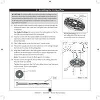
pilot holes into the wood support structure through the outermost holes in the outlet box. The pilot holes should be 9/64" in diameter. For Angled Ceilings: Be sure to orient the ceiling plate so that the two tabs are pointing toward the ceiling peak. 2-2. Your fan comes with four preinstalled - Hunter 21313 | Owner's Manual - Page 6
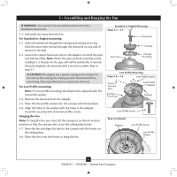
in the adapter. Assemble securely with three low profile screws. Hanging the Fan: Note: To hang the fan, you must tilt the canopy to an almost vertical position so that the canopy slots sit on the ceiling plate hooks. 3-7. Raise the fan and align the slots in the canopy with the hooks on the - Hunter 21313 | Owner's Manual - Page 7
and push them carefully back through the ceiling plate into the outlet box. 4-7. Spread the wires apart, with the grounded wires on one side of the outlet box and the ungrounded wires on the other side of the outlet box. 7 42666-01 • 10/29/08 • Hunter Fan Company fsdfsdf Wire Connector Dual Switch - Hunter 21313 | Owner's Manual - Page 8
hanger ball groove. Note: Your fan may have multiple tabs and grooves that must be aligned. 5-2. Swing the fan up to align the canopy screw holes with the mounting holes on the ceiling plate. WARNING: The slots Step 5-3 Canopy Canopy Trim Ring Canopy Screw 8 42666-01 • 10/29/08 • Hunter Fan Company - Hunter 21313 | Owner's Manual - Page 9
securely. You will feel it lock into place. 6-4. Repeat steps 6-1 through 6-3 until all blades are installed. Open Step 6-1 Close Step 6-3 9 42666-01 • 10/29/08 • Hunter Fan Company - Hunter 21313 | Owner's Manual - Page 10
Hunter fan comes with an integrated light fixture assembly and an optional switch housing cap and plug button. This feature gives you the option of installing the fan performance of the fan and will void the warranty. WARNING: Use only the light fixture supplied with this fan model. CAUTION: Make - Hunter 21313 | Owner's Manual - Page 11
switch housing with three housing assembly screws. Lower Switch Housing Plug Connector Steps 7-1 - 7-2 Plug Connector Detail Housing Assembly Screw 11 42666-01 • 10/29/08 • Hunter Fan Company - Hunter 21313 | Owner's Manual - Page 12
. Then, Thread the light pull chain through the hole in the center of the cover plate. 7-8. Thread the fan pull chain through the grommet hole in the side of the cover plate. 7-9. Place the cover plate up against Metal Rod Glass Bowl Cover Plate Finial 12 42666-01 • 10/29/08 • Hunter Fan Company - Hunter 21313 | Owner's Manual - Page 13
light fixture, continue with step 7‑1 Steps 7-13 - 7-15 Male Dummy Terminal Female Dummy Terminal Cap Plug Button Step 7-17 13 42666-01 • 10/29/08 • Hunter Fan Company - Hunter 21313 | Owner's Manual - Page 14
The chain has two settings: ON and OFF. 8-4. Ceiling fans work best by blowing air downward (counterclockwise blade rotation) fan off and let it come to a complete stop. Slide the reversing switch on the fan to the opposite position. Restart fan. Reversing Switch 14 42666-01 • 10/29/08 • Hunter Fan - Hunter 21313 | Owner's Manual - Page 15
blade is cracked. If so, replace all the blades. Problem: Excessive wobbling. 1. If your fan wobbles when operating, use the enclosed balancing kit and instructions to balance the fan. 2. Tighten all blade iron screws. 3. Turn power off, support fan very carefully, and check that the hanger ball is
-
 1
1 -
 2
2 -
 3
3 -
 4
4 -
 5
5 -
 6
6 -
 7
7 -
8
-
9
-
10
-
11
-
12
-
13
-
14
-
15
 |
 |
Type 2 Models
Type 2 Models
Type 2 Models
Form# 42666-01
20081029
©2008 Hunter Fan Co.
For Your Records and
Warranty Assistance
For reference, also attach your receipt or a copy
of your receipt to the manual.
__________________________________________
Model Name
__________________________________________
Model No.
__________________________________________
Catalog No.
__________________________________________
Date Purchased
__________________________________________
Where Purchased
English
Español
Owner’s Guide and Installation Manual