Hunter 21315 Owner's Manual
Hunter 21315 Manual
 |
View all Hunter 21315 manuals
Add to My Manuals
Save this manual to your list of manuals |
Hunter 21315 manual content summary:
- Hunter 21315 | Owner's Manual - Page 1
For Your Records and Warranty Assistance For reference, also attach your receipt or a copy of your receipt to the manual. Model Name Model No. Date Purchased Where Purchased Type 2 Models Owner's Guide and Installation Manual English Español Form# 45039-01 20101217 ©2010 Hunter Fan Co. - Hunter 21315 | Owner's Manual - Page 2
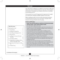
Cleaning Your Ceiling Fan 16 9 • Troubleshooting 17 Welcome Your new Hunter® ceiling fan is an addition to your home or office that will provide comfort and performance for many years. This installation and operation manual gives you complete instructions for installing and operating your fan. We - Hunter 21315 | Owner's Manual - Page 3
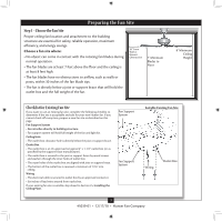
an approved connector. • Six inches of lead wires extend from outlet box. If your existing fan site is suitable, skip ahead to Section 2 • Installing the Ceiling Plate. Fan Support System Fan Support System Suitable Existing Fan Site Wiring Outlet Box 3 45039-01 • 12/17/10 • Hunter Fan Company - Hunter 21315 | Owner's Manual - Page 4
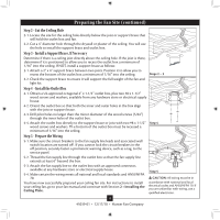
and outer holes in the box align with the joist or support brace. 4-3. Drill pilot holes no larger than the minor diameter ceiling fan site. For instructions to install your ceiling fan, go to your fan manual and continue with Section 2 • Installing the Ceiling Plate. Step 5 CAUTION: All wiring - Hunter 21315 | Owner's Manual - Page 5
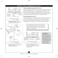
, follow the instructions included with each product. For quiet and optimum performance of your Hunter fan, use only Hunter speed controls. Support Brace Ceiling Outlet Box For ceilings higher than 8 feet, you can purchase Hunter extension downrods. All Hunter fans use sturdy 3/4" diameter - Hunter 21315 | Owner's Manual - Page 6
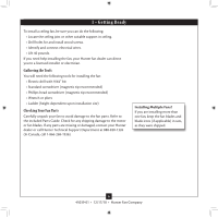
site) Checking Your Fan Parts Carefully unpack your fan to avoid damage to the fan parts. Refer to the included Parts Guide. Check for any shipping damage to the motor or fan blades. If any parts are missing or damaged, contact your Hunter dealer or call Hunter Technical Support Department at 888 - Hunter 21315 | Owner's Manual - Page 7
of the two 3" wood screws. 2-4. Thread the supply wires from the outlet box in the ceiling through the hole in the center of the ceiling plate. 2-5. Align the slotted holes in the ceiling plate with the pilot holes you drilled in the wood support structure. For proper alignment use slotted holes - Hunter 21315 | Owner's Manual - Page 8
directed in these installation instructions. 3-1. Unbundle the wires from the fan and remove the paper caution tag. Do not discard the tag until your installation is complete. For Standard or Angled mounting: 3-2. To assemble fan to hang down from a flat or angled ceiling, insert the downrod through - Hunter 21315 | Owner's Manual - Page 9
carefully back through the ceiling plate into the outlet box. 4-7. Spread the wires apart, with the grounded wires on one side of the outlet box and the ungrounded wires on the other side of the outlet box. 9 45039-01 • 12/17/10 • Hunter Fan Company Wire Connector Dual Switch Wiring Single Switch - Hunter 21315 | Owner's Manual - Page 10
hanger ball groove. Note: Your fan may have multiple tabs and grooves that must be aligned. 5-2. Swing the fan up to align the canopy screw holes with the mounting holes on the ceiling plate. WARNING: The slots in 5-3 Canopy Canopy Trim Ring Canopy Screw 10 45039-01 • 12/17/10 • Hunter Fan Company - Hunter 21315 | Owner's Manual - Page 11
. Insert the second blade mounting screw, then securely tighten both mounting screws. Step 6-1 (Detail) Grommet Note: The blades on this fan have been treated with Hunter's Dust Armor protection, making the blades less likely to attract dust and dirt. Use a dry or slightly damp lint free cloth to - Hunter 21315 | Owner's Manual - Page 12
Hunter fan comes with an integrated light fixture assembly and an optional switch housing cap and plug button. This feature gives you the option of installing the fan fixture. WARNING: Use only the light fixture supplied with this fan model. 7-1. To attach the upper switch housing, partially install - Hunter 21315 | Owner's Manual - Page 13
switch housing with three housing assembly screws. Steps 7-6 - 7-7 Lower Switch Housing Note: In compliance with US federal energy regulations, this ceiling fan contains a device that restricts its light output. Exceeding the wattage limit marked on the MAX wattage sticker affixed to the light - Hunter 21315 | Owner's Manual - Page 14
) into the sockets. 7-9. Thread the light and fan pull chains through the hole in the center of center of the cover plate. 7-10. Thread the fan pull chain through the grommet hole in the side of extra pull chains (included) to the light and fan pull chains using the breakaway connector. (You may find - Hunter 21315 | Owner's Manual - Page 15
connector (female) through the hole. 7-19. Install the dummy terminals (included in the sack parts) on the two disconnected wires in the lower switch housing. 7-20. Install the switch housing cap and plug button to Terminal Cap Plug Button Step 7-20 15 45039-01 • 12/17/10 • Hunter Fan Company - Hunter 21315 | Owner's Manual - Page 16
light. The pull chain has two settings: On and Off. 8-4. Ceiling fans work best by blowing air downward (counterclockwise blade rotation) in warm weather they will damage the finish. 8-6. The blades on this fan have been treated with Hunter's Dust Armor protection, making the blades less likely to - Hunter 21315 | Owner's Manual - Page 17
9 • Troubleshooting Problem: Nothing happens; fan does not move 1. Turn power on, replace fuse, or reset breaker. 2. Loosen canopy, check all connections according to the wiring the fan section. 3. Check the plug connection in the switch housing. 4. Push motor reversing switch firmly left or right
-
 1
1 -
 2
2 -
 3
3 -
 4
4 -
 5
5 -
 6
6 -
 7
7 -
8
-
9
-
10
-
11
-
12
-
13
-
14
-
15
-
16
-
17
 |
 |

Type 2 Models
Type 2 Models
Type 2 Models
Form# 45039-01
20101217
©2010 Hunter Fan Co.
For Your Records and
Warranty Assistance
For reference, also attach your receipt or a copy
of your receipt to the manual.
__________________________________________
Model Name
__________________________________________
Model No.
__________________________________________
Date Purchased
__________________________________________
Where Purchased
English
Español
Owner’s Guide and Installation Manual