Hunter 21317 Owner's Manual
Hunter 21317 Manual
 |
View all Hunter 21317 manuals
Add to My Manuals
Save this manual to your list of manuals |
Hunter 21317 manual content summary:
- Hunter 21317 | Owner's Manual - Page 1
For Your Records and Warranty Assistance For reference, also attach your receipt or a copy of your receipt to the manual. Model Name Model No. Date Purchased Where Purchased Type 7 Models Owner's Guide and Installation Manual English Español Form# 45032-01 20110121 ©2011 Hunter Fan Co. - Hunter 21317 | Owner's Manual - Page 2
Cleaning Your Ceiling Fan 17 9 • Troubleshooting 18 Welcome Your new Hunter® ceiling fan is an addition to your home or office that will provide comfort and performance for many years. This installation and operation manual gives you complete instructions for installing and operating your fan. We - Hunter 21317 | Owner's Manual - Page 3
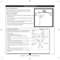
and safe for your new Hunter fan. If you cannot check off every item, prepare a new fan site as described on this page. Fan Support System • Fan attaches directly to building structure. • Fan support system will hold full weight of the fan and light kit. Ceiling Hole • e outlet box clearance hole - Hunter 21317 | Owner's Manual - Page 4
support service panel. 5-2. read the fan supply line through the outlet box so that the fan supply line extends at least 6" beyond the box. 5-3. Attach the fan ceiling fan site. For instructions to install your ceiling fan, go to your fan manual and continue with Section 2 • Installing the Ceiling - Hunter 21317 | Owner's Manual - Page 5
, follow the instructions included with each product. For quiet and optimum performance of your Hunter fan, use only Hunter speed controls. Support Brace Ceiling Outlet Box For ceilings higher than 9 feet, you can purchase Hunter extension downrods. All Hunter fans use sturdy 3/4" diameter - Hunter 21317 | Owner's Manual - Page 6
To install a ceiling fan, be sure you can do the following: • Locate the ceiling joist or other suitable support in ceiling. • Drill holes for and install wood screws. • Identify and connect electrical wires. • Lift 40 pounds. If you need help installing the fan, your Hunter fan dealer can direct - Hunter 21317 | Owner's Manual - Page 7
wood support structure. For proper alignment use slotted holes directly across from each other. If you are installing the fan on an ANGLED ceiling, be Ceiling Peak Large Opening OR Steps 2-2 - 2-4 Ceiling Peak Large Opening LEFT Step 2-3 (Angled Ceiling Only) 7 45032-01 • 01/21/11 • Hunter Fan - Hunter 21317 | Owner's Manual - Page 8
bracket. (Rotate the fan until you hear the notch pop into place.) Go to 4 • Wiring the Fan. Steps 3-4 - 3-5 WARNING: Fan may fall if not assembled as directed in these installation instructions. Downrod Canopy Canopy Trim Ring Setscrew Indent 8 45032-01 • 01/21/11 • Hunter Fan Company - Hunter 21317 | Owner's Manual - Page 9
You can assemble your fan for standard or angled mounting as shown in steps 3-1 - 3-3 on the previous page. For low profile mounting (ceilings less than 9 the rim of the canopy. WARNING: Fan may fall if not assembled as directed in these installation instructions. Step 3-6 (Not Actual Size) - Hunter 21317 | Owner's Manual - Page 10
the wire connectors upward and push them carefully back through the ceiling plate into the outlet box. 4-7. Spread the wires apart, with the grounded wires on one side of the outlet box and the ungrounded wires on the other side of the outlet box. 10 45032-01 • 01/21/11 • Hunter Fan Company - Hunter 21317 | Owner's Manual - Page 11
trim ring counter clockwise until it releases from canopy. Hanger Bracket Canopy Trim Ring Step 5-4 Step 5-3 Step 5-5 Canopy Screw 11 45032-01 • 01/21/11 • Hunter Fan Company - Hunter 21317 | Owner's Manual - Page 12
. Insert the second blade mounting screw, then securely tighten both mounting screws. Step 6-1 (Detail) Grommet Note: The blades on this fan have been treated with Hunter's Dust Armor protection, making the blades less likely to attract dust and dirt. Use a dry or slightly damp lint free cloth to - Hunter 21317 | Owner's Manual - Page 13
Hunter fan comes with an integrated light fixture assembly and an optional switch housing cap and plug button. This feature gives you the option of installing the fan fixture. WARNING: Use only the light fixture supplied with this fan model. 7-1. To attach the upper switch housing, partially install - Hunter 21317 | Owner's Manual - Page 14
with three housing assembly screws. Steps 7-6 - 7-7 Lower Switch Housing Plug Connector Note: In compliance with US federal energy regulations, this ceiling fan contains a device that restricts its light output. Exceeding the wattage limit marked on the MAX wattage sticker affixed to the light - Hunter 21317 | Owner's Manual - Page 15
, Thread the light pull chain through the hole in the center of the cover plate. 7-12. Thread the fan pull chain through the grommet hole in the side of the cover plate. 7-13. Place the cover plate up Glass Bowl Breakaway Connector Cover Plate Finial 15 45032-01 • 01/21/11 • Hunter Fan Company - Hunter 21317 | Owner's Manual - Page 16
, continue with step 7‑6. Lower Switch Housing Step 7-18 Male Dummy Terminal Female Dummy Terminal Cap Plug Button Step 7-21 16 45032-01 • 01/21/11 • Hunter Fan Company - Hunter 21317 | Owner's Manual - Page 17
light fixture. The chain has two settings: ON and OFF. 8-4. Ceiling fans work best by blowing air downward (counterclockwise blade rotation) in warm they will damage the finish. 8-6. The blades on this fan have been treated with Hunter's Dust Armor protection, making the blades less likely to - Hunter 21317 | Owner's Manual - Page 18
blade is cracked. If so, replace all the blades. Problem: Excessive wobbling. 1. If your fan wobbles when operating, use the enclosed balancing kit and instructions to balance the fan. 2. Tighten all blade iron screws. 3. Turn power off, support fan very carefully, and check that the hanger ball is
-
 1
1 -
 2
2 -
 3
3 -
 4
4 -
 5
5 -
 6
6 -
 7
7 -
8
-
9
-
10
-
11
-
12
-
13
-
14
-
15
-
16
-
17
-
18
 |
 |

Type 7 Models
Type 7 Models
Type 7 Models
Form# 45032-01
20110121
©2011 Hunter Fan Co.
For Your Records and
Warranty Assistance
For reference, also attach your receipt or a copy
of your receipt to the manual.
__________________________________________
Model Name
__________________________________________
Model No.
__________________________________________
Date Purchased
__________________________________________
Where Purchased
English
Español
Owner’s Guide and Installation Manual