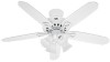
Hunter 25746 Owner's Manual
Hunter 25746 Manual
 |
View all Hunter 25746 manuals
Add to My Manuals
Save this manual to your list of manuals |
Hunter 25746 manual content summary:
- Hunter 25746 | Owner's Manual - Page 1
For Your Records and Warranty Assistance For reference, also attach your receipt or a copy of your receipt to the manual. Model Name Model No. Date Purchased Where Purchased Type 2 Models Owner's Guide and Installation Manual English Español Form# 42419-01 20081124 ©2008 Hunter Fan Co. - Hunter 25746 | Owner's Manual - Page 2
the Remote Control _ and Mounting the Holder 14 10 • Operating and Cleaning Your _ Ceiling Fan 15 11 • Troubleshooting 16 Welcome Your new Hunter® ceiling fan is an addition to your home or office that will provide comfort and performance for many years. This installation and operation manual - Hunter 25746 | Owner's Manual - Page 3
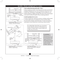
, including a wall-mounted or remote speed control. To install and use the accessories, follow the instructions included with each product. For quiet and optimum performance of your Hunter fan, use only Hunter speed controls. Support Brace Ceiling Outlet Box For ceilings higher than 8 feet, you - Hunter 25746 | Owner's Manual - Page 4
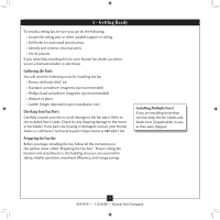
. If any parts are missing or damaged, contact your Hunter dealer or call Hunter Technical Support Department at 888-830-1326. Preparing the Fan Site Before you begin installing the fan, follow all the instructions in the pullout sheet called "Preparing the Fan Site." Proper ceiling fan location and - Hunter 25746 | Owner's Manual - Page 5
into the wood support structure through the outermost holes in the outlet box. The pilot holes should be 9/64" Ceiling in diameter. Plate 2-2. Your fan comes with two neoprene noise isolators ("Isolators"). Position the isolators between the ceiling plate and ceiling by inserting the raised - Hunter 25746 | Owner's Manual - Page 6
. Go to 4 • Wiring the Fan. WARNING: Fan may fall if not assembled as directed in these installation instructions. Steps 3-1 - 3-2 Setscrew Steps 3-3 - 3-4 Ceiling Plate Tabs Step 3-5 Downrod Canopy Low Profile Washer #8-32 x 1" Screw Canopy Slots 6 42419-01 • 11/24/08 • Hunter Fan Company - Hunter 25746 | Owner's Manual - Page 7
them carefully back through the ceiling plate into the outlet box. 4-7. Spread the wires apart, with the grounded wires on one side of the outlet box and the ungrounded wires on the other side of the outlet box. fsdfsdf Wire Connector Single Switch Wiring 7 42419-01 • 11/24/08 • Hunter Fan Company - Hunter 25746 | Owner's Manual - Page 8
could cause fan to fall. 5-2. Lift the fan and align the canopy screw holes with the mounting holes on the ceiling plate. 5-3. Partially install a canopy screw into the side opposite the ceiling plate tabs. trim ring from the canopy. Step 5-4 Step 5-5 8 42419-01 • 11/24/08 • Hunter Fan Company - Hunter 25746 | Owner's Manual - Page 9
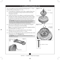
Blades Hunter fans use several styles of fan blade irons (brackets that hold the blade to the fan). 6-1. Your fan may include blade grommets. If your fan has mounting screw through the blade iron, and attach lightly to the fan. Insert the second blade mounting screw, then securely tighten both - Hunter 25746 | Owner's Manual - Page 10
aappaaggaaddoo)) 31 == oonn ((eenncceennddiiddoo)) 2 = off (apagado) 1 = on (encendido) CAUTION: The remote control device complies with part 15 of the FCC rules. Changes or modifications not expressly approved by Hunter Fan Company could void your authority to operate this equipment. Operation is - Hunter 25746 | Owner's Manual - Page 11
Your Installation With or Without a Multi Staked Light Fixture Your Hunter fan comes with an integrated light fixture assembly and an optional switch housing cap and plug button. This feature gives you the option of installing the fan with OR without the included light fixture. The steps below - Hunter 25746 | Owner's Manual - Page 12
Note: Glass shade style and number of lights may vary. Housing Assembly Screw Thumbscrews Note: In compliance with US federal energy regulations, this ceiling fan contains a device that restricts the light kit to a maximum of 190 Watts. Exceeding that limit or the marked limit on this product may - Hunter 25746 | Owner's Manual - Page 13
the upper switch housing with three #6-32 x 1/2" housing assembly screws. Housing Assembly Screw Steps 8-10 - 8-11 Plug Connector Detail 13 42419-01 • 11/24/08 • Hunter Fan Company - Hunter 25746 | Owner's Manual - Page 14
9 • Operating the Remote Control and Mounting the Holder 9-1. The remote transmitter has individual buttons for turning the fan off and on and controlling the light and fan speed. 9-2. For best operation, start the fan by pressing high, then select your desired speed. 9-3. The light button turns - Hunter 25746 | Owner's Manual - Page 15
pull chain controls the power to the light fixture. The chain has two settings: ON and OFF. 10-4. Ceiling fans work best fan off and let it come to a complete stop. Slide the reversing switch on the fan to the opposite position. Restart fan. Reversing Switch 15 42419-01 • 11/24/08 • Hunter Fan - Hunter 25746 | Owner's Manual - Page 16
off, support fan very carefully, and check that the hanger ball is properly seated. Problem: Lights dim when turned on or do not turn on 1. Check to make sure the wattage and type of light bulbs installed match the specifications on the light socket. If you need parts or service assistance, please
-
 1
1 -
 2
2 -
 3
3 -
 4
4 -
 5
5 -
 6
6 -
 7
7 -
8
-
9
-
10
-
11
-
12
-
13
-
14
-
15
-
16
 |
 |
Type 2 Models
Type 2 Models
Type 2 Models
Form# 42419-01
20081124
©2008 Hunter Fan Co.
For Your Records and
Warranty Assistance
For reference, also attach your receipt or a copy
of your receipt to the manual.
__________________________________________
Model Name
__________________________________________
Model No.
__________________________________________
Date Purchased
__________________________________________
Where Purchased
English
Owner’s Guide and Installation Manual
Español