Hunter 25867 Owner's Manual
Hunter 25867 Manual
 |
View all Hunter 25867 manuals
Add to My Manuals
Save this manual to your list of manuals |
Hunter 25867 manual content summary:
- Hunter 25867 | Owner's Manual - Page 1
For Your Records and Warranty Assistance For reference, also attach your receipt or a copy of your receipt to the manual. Model Name Model No. Date Purchased Where Purchased Type T Models Owner's Guide and Installation Manual English Español Form# 42774-01 20090612 ©2009 Hunter Fan Co. - Hunter 25867 | Owner's Manual - Page 2
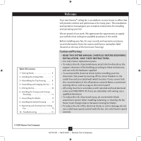
and Cleaning Your Ceiling Fan 14 10 • Troubleshooting 15 Welcome Your new Hunter® ceiling fan is an addition to your home or office that will provide comfort and performance for many years. This installation and operation manual gives you complete instructions for installing and operating - Hunter 25867 | Owner's Manual - Page 3
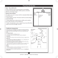
and safe for your new Hunter fan. If you cannot check off every item, prepare a new fan site as described on this page. Fan Support System • Fan attaches directly to building structure. • Fan support system will hold full weight of the fan and light kit. Ceiling Hole • e outlet box clearance hole - Hunter 25867 | Owner's Manual - Page 4
both the inner and outer holes in the box align with the joist or support brace. 4-3. Drill pilot holes no larger than the minor diameter of the wood your ceiling fan site. For instructions to install your ceiling fan, go to your fan manual and continue with Section 2 • Installing the Ceiling Plate - Hunter 25867 | Owner's Manual - Page 5
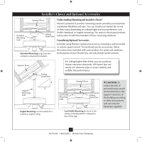
, follow the instructions included with each product. For quiet and optimum performance of your Hunter fan, use only Hunter speed controls. Support Brace Ceiling Outlet Box For ceilings higher than 8 feet, you can purchase Hunter extension downrods. All Hunter fans use sturdy 3/4" diameter - Hunter 25867 | Owner's Manual - Page 6
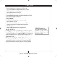
missing or damaged, contact your Hunter dealer or call Hunter Technical Support Department at 888-830-1326. Preparing the Fan Site Before you begin installing the fan, follow all the instructions in the pullout sheet called "Preparing the Fan Site." Proper ceiling fan location and attachment to the - Hunter 25867 | Owner's Manual - Page 7
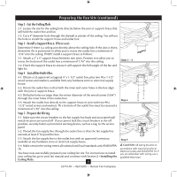
the screws. Do not over tighten. Isolator Ceiling Plate Flat Washer Step 2-2 Steps 2-3 - 2-5 3" Wood Screw For Angled Ceilings: Be sure to orient the ceiling plate so that the arrows printed on the ceiling plate are pointing toward the ceiling peak. 7 42774-01 • 06/12/09 • Hunter Fan Company - Hunter 25867 | Owner's Manual - Page 8
flat on the adapter. 3-2. Install three (3) assembly screws (#8-32) and tighten them securely. Steps 3-1 - 3-2 Top Housing Assembly Screw Hanger Adapter 8 42774-01 • 06/12/09 • Hunter Fan Company - Hunter 25867 | Owner's Manual - Page 9
Fan WARNING: Fan may fall if not assembled as directed in these installation instructions. 4-1. Unbundle the wires from the fan. For Standard or Angled mounting: 4-2. To assemble fan to hang down from a flat or angled ceiling ceiling. 4-6. Align the holes fan and place the hook on the ceiling - Hunter 25867 | Owner's Manual - Page 10
carefully back through the ceiling plate into the outlet box. 5-7. Spread the wires apart, with the grounded wires on one side of the outlet box and the ungrounded wires on the other side of the outlet box. fsdfsdf Wire Connector Single Switch Wiring 10 42774-01 • 06/12/09 • Hunter Fan Company - Hunter 25867 | Owner's Manual - Page 11
tabs. 2. Press firmly on opposite sides of the ring toward the canopy. The tabs will flex out releasing the trim ring from the canopy. Steps 6-4 - 6-5 Ceiling Plate Canopy Trim Ring Step 6-3 Canopy Screw 11 42774-01 • 06/12/09 • Hunter Fan Company - Hunter 25867 | Owner's Manual - Page 12
7 • Assembling the Blades 7-1. Attach each blade to the fan using three blade assembly screws. Step 7-1 Blade Assembly Screw 12 42774-01 • 06/12/09 • Hunter Fan Company - Hunter 25867 | Owner's Manual - Page 13
two parts. All wiring must be tucked up inside the switch housing. Switch Housing Cover 8-3. Complete the fan assembly by attaching the small round cover to the bottom of the switch housing cover. First Screw insert Pull Chain Screw Switch Housing Cap 13 42774-01 • 06/12/09 • Hunter Fan Company - Hunter 25867 | Owner's Manual - Page 14
simply reinsert the chain into the connector. 9-3. Ceiling fans work best by blowing air downward (counterclockwise blade fan off and let it come to a complete stop. Slide the reversing switch on the fan to the opposite position. Restart fan. Reversing Switch 14 42774-01 • 06/12/09 • Hunter Fan - Hunter 25867 | Owner's Manual - Page 15
blade is cracked. If so, replace all the blades. Problem: Excessive wobbling. 1. If your fan wobbles when operating, use the enclosed balancing kit and instructions to balance the fan. 2. Tighten all blade iron screws. 3. Turn power off, support fan very carefully, and check that the hanger ball is
-
 1
1 -
 2
2 -
 3
3 -
 4
4 -
 5
5 -
 6
6 -
 7
7 -
8
-
9
-
10
-
11
-
12
-
13
-
14
-
15
 |
 |
Type T Models
Type T Models
Type T Models
Form# 42774-01
20090612
©2009 Hunter Fan Co.
For Your Records and
Warranty Assistance
For reference, also attach your receipt or a copy
of your receipt to the manual.
__________________________________________
Model Name
__________________________________________
Model No.
__________________________________________
Date Purchased
__________________________________________
Where Purchased
English
Español
Owner’s Guide and Installation Manual